

Cleanup and repair of a Hewlett Packard (HP) 8012B pulse generator purchased on Ebay as “Untested does not power on, sold as is”.
The 8012B was originally produced by the HP Gmbh Boeblingen Divison, Germany, but this later model was made in USA. It provides variable transition times down to 5 ns and the repetition rate can be adjusted from 1 Hz to 50 MHz.
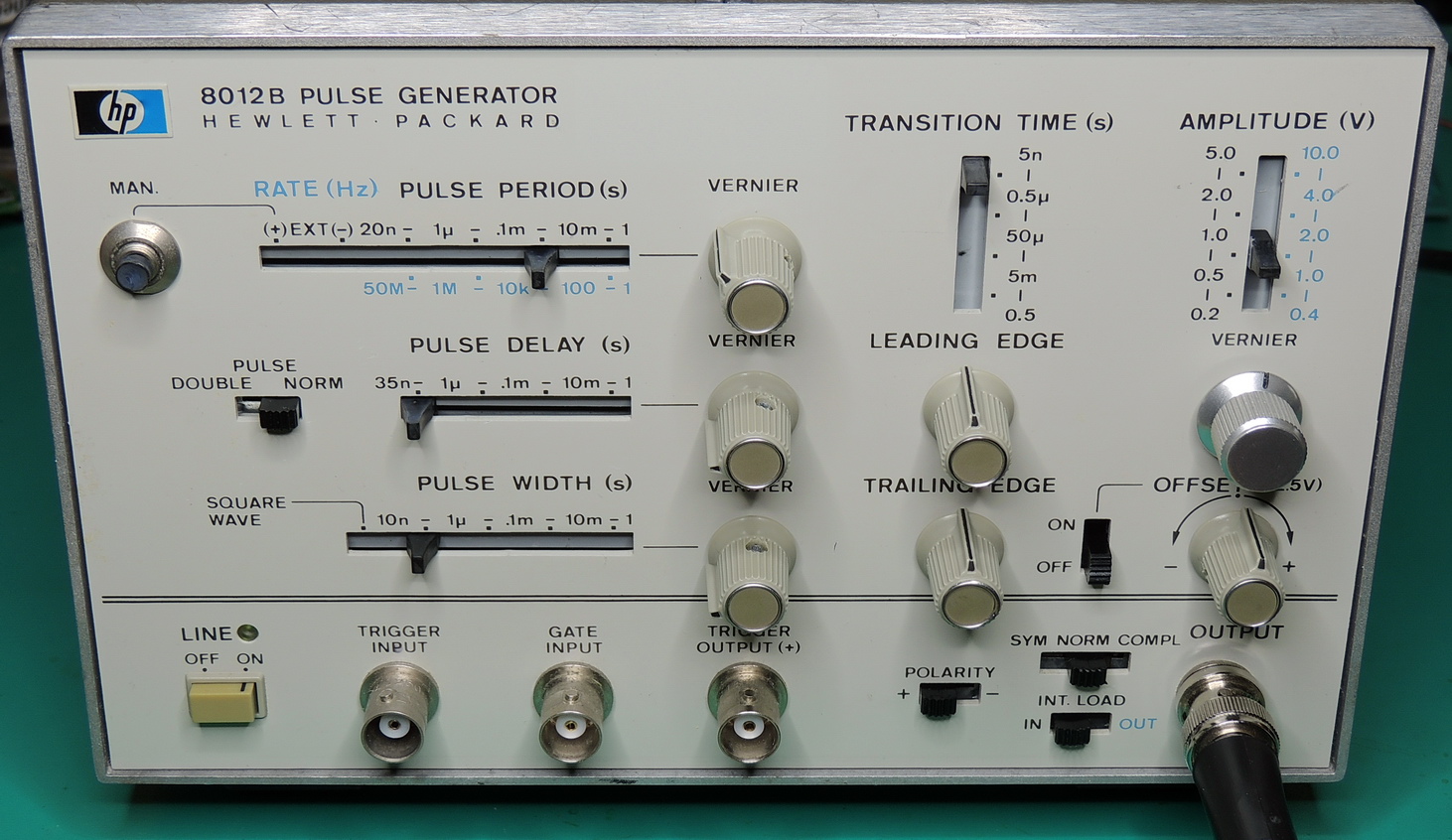
I was able to pick up this supposedly broken 8012B on Ebay for under $15 USD, plus about the same amount for shipping. As usual the front panel of the unit was covered with label residue and a ID label, plus plenty of protective grime. There was only one broken knob, but other than that the unit looked in overall good condition for it’s age.
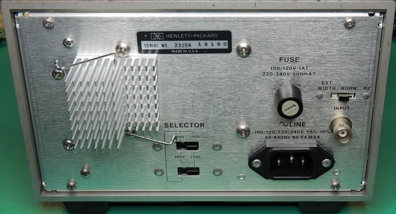
After receiving the unit I gave it a quick inspection for items such as the correct fuse, back panel voltage setting, transformer primary and secondary resistance readings, power supply filter capacitor in-circuit checks, power supply diode checks, and an overall visual inspection of all boards and connections.
Everything checked out great, so I powered it up…
It was very uneventful. There was no “Line” power indicator lit up on the front panel or any other signs of life, but my Watts up? Pro power line meter showed a steady 390 mA being used at 120 VAC. I quickly turned on my TDS 340A oscilloscope, and after adjusting some front panel settings I had a pulse waveform on the display. All of the front panel switches were very intermittent and noisy, but the unit seemed to be working.

As soon as I purchased the unit I ordered new electrolytic capacitors for the power supply, since I knew that this was a mid-80’s unit. Date codes on the internal components indicate that this unit was produced in early 1986, and sold for $1,500 in 1982 which is equivalent to $4,450 in 2022 dollars. I used a pair of Nichicon 1,500 uF 63 volt axial capacitors rated for 105 degrees C for C29 & C30, and had a new-old-stock Sprague 100 uF 25 volt capacitor for C45.

I also ended up replacing all the film capacitors on the A5 and A6 boards, because they looked a bit crusty and suspicious. After removal, all of the film capacitors checked out good and were well within tolerance, but I had some higher quality spares and still wasn’t impressed with the epoxy deterioration of the original components.

Up next was the non-functioning front panel “Line” indicator. The original lamp was a T1 28 volt incandescent bulb. The lamp is powered by the plus and minus 17 volt power supplies for a total of 34 volts DC. There is a 270 ohm dropping resistor R33 in series with the 28 volt bulb. I replaced R33 with a 4K ohm resistor, and used a green T‑1 LED as a replacement. The cathode was soldered to the plated thru-hole ring and anode was attached to the new resistor.

The only adjustments that I made were to the trim-pots for the +/- 17 volt power rails. As per the manual instructions I set the power rails as close to 17 volts as possible using the recommended test points on A6.

The voltages in other areas of the A6 board were very close to the set voltages, but when checking the A5 board I noticed a drop in voltage on the power rails. Some of this drop is to be expected as the A5 board is further away from the power source. Upon closer inspection of the A5 board, I noticed the use of some very small circuit traces from the edge card connections.
My fix was to use some silver coated PTFE wire to jumper the limiting circuit traces to provide an additional and better current path for circuits deeper in the A5 board. I did this for both plus and minus power rails.

The next hurdle was to gain access to the front panel slide switches.
To properly clean the switches the front panel needs to be removed, which is not an easy task. The output BNC needs to be unsoldered, and all potentiometer knobs and mounting nuts should be removed along with numerous Pozidriv screws on the back of the panel. I then carefully removed the sliding contacts and carrier knobs where possible. The grease had become extremely viscous over time and took some time to remove with isopropyl alcohol. After a thorough cleaning I used used DeoxIT D5 for the enclosed switches and for a final cleaning of the dissembled slide switches as it also provides some lubrication after it dries.
I was so frustrated while removing the front panel I forgot to take pictures. I don’t want to do that again anytime soon.

The remaining issue was a very hard to turn Amplitude vernier control. This is where the broken knob resided, and was probably the reason for it’s demise. I used some low viscosity sewing machine oil where the shaft enters the potentiometer, and some DeoxIT D5 inside the dual 50 ohm potentiometer, then rotated the shaft. This was done several days in a row, until the shaft turned freely..

I ran through all the performance checks in the service manual, and didn’t need to make any adjustments. The HP 8012B is not an easy unit to work on, but it performs very well.

While doing a final inspection of the pulse generator, I decided to replace the 36 year old Corcom power line input filter with a new Schurter filter #5110.0333.1.
While I had the power leads disconnected, I also added some heatshrink tubing around the exposed conductors on the fuse holder.


Here are some saved images from the TDS 340A oscilloscope:


I am currently saving up my coffee money to hopefully acquire a HP 8082A which features transition times over a range of 1 ns to 5 ms, and pulse repetition rates as high as 250 MHz.
Higher-resolution images available in my Flicker HP 8012B album