

Several decades ago I owned two Beckman / Berkeley model 7360–20 Universal EPUT® and Timer’s. Because of their size and weight and an upcoming move, I gave them away to a friend. In the past few years I have somewhat regretted that decision, even though it was probably for the best. So when I saw this 7360 up for auction, I decided to make an offer on it. I was able to purchase it at a reasonable price, but as expected the shipping was a bit high due to it’s size and weight.
So what is a “Universal EPUT® and Timer”?
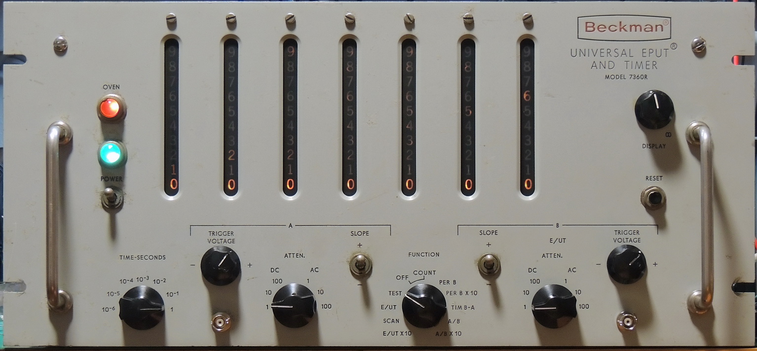
It is an electronic counter which performs a wide variety of frequency and time measurements. The EPUT® part of the description is an acronym for “Events Per Unit of Time“
EPUT® Meters automatically count and display the number of events that occur during a precise time interval, also known as Frequency.
The 7360R will measure frequencies up to 1 MHz, and time measurements in one μ‑second units, along with time interval between events on separate channels, manually controlled event counter, time interval and phase difference on separate channels, extended Scan interval, and self-test check.
In my opinion, pretty impressive for a 52 vacuum tube and 70 neon bulb piece of test equipment designed in the mid 1950’s. This unit was produced in the later part of 1962 going by the date codes on some of the components.

The unit arrived in good shape considering it’s weight, with only it’s top cover coming loose during transport. All of the tubes were still in their sockets with no visual damage.
The original power cord had been severed, so I was fairly sure that it had not been powered up in many years or possibly decades. The unit had been stored in non-optimal conditions and was very dirty with rust spots and corrosion in several areas. Time to start the long arduous task of cleaning inside and out.

The dirtiest area was the divider adjustment bracket which is located on top of the unit and not protected by a cover. I ended up unsoldering the test point jacks and removing the potentiometers and wiring harness so that the rail could get a good scrub down. While I had the bracket off I also removed the side panel to clean in some hard to reach places.

During my cleaning I came across several of these blue Hopkins type MPA film capacitors that had developed cracks in their outer shells. Most of these were across the +120 volt power circuit feeding several different point of use circuits on the unit.
After seeing this I decided to replace all the electrolytic and paper dielectric film capacitors in the unit.

Another area of concern was the Selenium full-wave bridge rectifier used in the -110 volt power supply. Selenium rectifiers do not age well and this one needed to be replaced. The issue when replacing Selenium rectifiers is their higher voltage drop when compared to modern silicon rectifiers. I ended up changing the two parallel 22 Ohm 2 watt resistors (R111 and R112) with two 43 Ohm 3 watt resistors in parallel for a total of 21.5 Ohms vs the original 11 Ohms. It took me several tries to find the right combination as I started off with a higher resistance so as to not to end up with too high of a voltage initially.

I used a VS-KBPC608PBF Vishay Silicon rectifier rated at 800 volts and 8 amps which allowed me to mount it in the same location and use the case as a heat sink.

The two fuse holders for the 117 volt AC line were missing their caps and so were replaced with new Bussmann HKP-E-HH fuse holders, along with a new power cord.
The +120 power supply uses four 1N1084 cartridge style Silicon rectifiers rated at 500 mA and 400 volts each in a full-wave bridge configuration.
I also moved the main transformer power input terminal from #1 (117 volts) to #2 (126 volts) as my average house voltage is usually 125 volts. The transformer was manufactured by Oeco Corp. for Berkeley Scientific which is a division of Beckman Instruments Inc.
There are two 6.3 volt secondary AC windings. The 15 amp 6.3 volt winding is grounded on pin #8 and the 12 amp 6.3 volt winding is connected to the minus 110 volt DC supply on pin #10.
As an initial test I disconnected the 97 and 176 volt AC secondary windings from their respective rectifiers so that I could check the filaments on all the tubes.

All the tube filaments worked with no issues.
After a bit of a wait for my parts order it was time to get the selected capacitors replaced.
I opted for leaving the two original electrolytic 125 uF at 350 volt can capacitors (C101 & C106) in place and isolating the positive terminal on both capacitors. C106 on the negative 110 volt power rail has a completely isolated can from case ground.


The 1 MHz frequency divider circuit had 5 crusty components which at first I thought were leaky capacitors, but they turned out to be 3.9 Meg Ohm 1 watt 1 % precision resistors used in the adjustment of each decade divider. Most likely they originally had a conformal coating that had deteriorated over time. They were replaced along with (C612, C615, C617) the 0.0047 uF, 0.047 uF, and 0.47 uF paper film capacitors.


Now that all the necessary capacitors had been replaced it was time to tackle the DCU’s (Decimal Counting Units). The Beckman 7360R uses two types of DCU’s, the 785A which is capable of counting at a 1.1 MHz rate and only used in the A207 position as it’s cascaded output is one-tenth of it’s input rate.


The 785A cascades into six 775 DCU’s in series. The 775 has a maximum counting rate of 120,000 counts per second and like the 785A has a direct readout from 0 to 9 using neon bulbs to backlight the number being displayed.

Both types of DCU’s utilize four dual triode vacuum tubes which make up four flip-flop circuits per DCU. The 785A uses type 12AV7 tubes while the 775 DCU uses type 5963 tubes.
Other than a good cleaning no other maintenance was needed for the DCU’s. I did label each DCU so that I could get them back into their original sockets.

With all the tubes and DCU’s installed it was time to perform a full system power up test. I used a Variac to slowly bring up the AC line voltage while monitoring the power supply DC voltages with three multimeters.
All of the voltages ended up well within specifications, and I fine tuned the +120 volt supply using the adjustment on the back panel to exactly +120.0 volts.
I also had numbers displayed on the front panel, even though they were not quite correct, which I somewhat expected with all the components replaced and adjustment potentiometers moved while cleaning them. I did try to put the potentiometer’s back in their original positions after cleaning, but they almost never end up exactly where they started.

I was also monitoring the crystal time base frequency using the back panel BNC frequency output J401 during testing and noticed that the frequency did not level out at the specified 1 MHz and continued to drop. I also noticed that the crystal oven was not turning off so the system was powered down.

This 7360R uses a heated oven crystal frequency standard type SA 1078 made by Monitor Products Company of So. Pasadena, California. It uses a 115 volt AC heater element of around 900 Ohms and produces approximately 14.5 watts of heat. For temperature control it uses a hermetically sealed bi-metallic thermostat.

I had originally thought that the contacts in the thermostat were sticking, but it ended up being the suppression capacitor placed across the thermostat contacts. The capacitor was very shorted at 0.06 Ohms and only rated at 85 ℃ with a capacitance of 0.01 uF at 400 volts DC. It was also wrapped inside the fiberglass insulation against the heating element.


I was able to mount a new 105 ℃ rated capacitor so that the fiberglass insulation could be wrapped between it and the heating element providing a bit more thermal isolation.
After reassembling the crystal oven it was plugged in to the Y401 socket for another system test.

The crystal frequency standard was now switching the oven on and off to regulate it’s temperature. After 45 minutes of warm-up time I was able to use the “XTAL ADJ.” screw to set the frequency to within 0.1 Hz using my HP 5305B / 5300B external GPS disciplined frequency counter.

Now that I had a good frequency standard I was able to follow the calibration procedures in the service manual. After about an hour of adjusting the Shaper, Divider, and Attenuator circuits I had a working Beckman Universal EPUT® and Timer.

Well now that I have it running, what do I do with it?
Due to it’s size it won’t end up on the workbench equipment shelves, but I do have some display / unfrequently used equipment shelves with power where it will reside. Hopefully it will find some use when troubleshooting some equally vintage test equipment in the future. And if nothing else it will most likely bring a smile to my face on a cold rainy day when I power it on to view the warm glow of the Neon digits on it’s display.


As a novice electronics experimenter, I purchased one of these at a flea market in the mid 70s. I am sure that the seller had no clue what it was. Think I paid $10 for it, and at that price, I didn’t have much to loose if it didn’t work.
It was in good physical condition and after a few tube replacements it seemed to work well.
I didn’t have much for test equipment to completely check it, but was satisfied that it was good enough for a beginner.
Looking back, it was a fascinating piece of equipment that I enjoyed using.
After being employed in electrical engineering, I gave away all my home lab stuff as I had better stuff to play with. But I do think back fondly on that Beckman.