

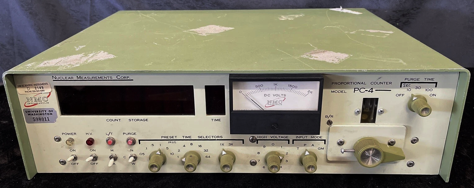
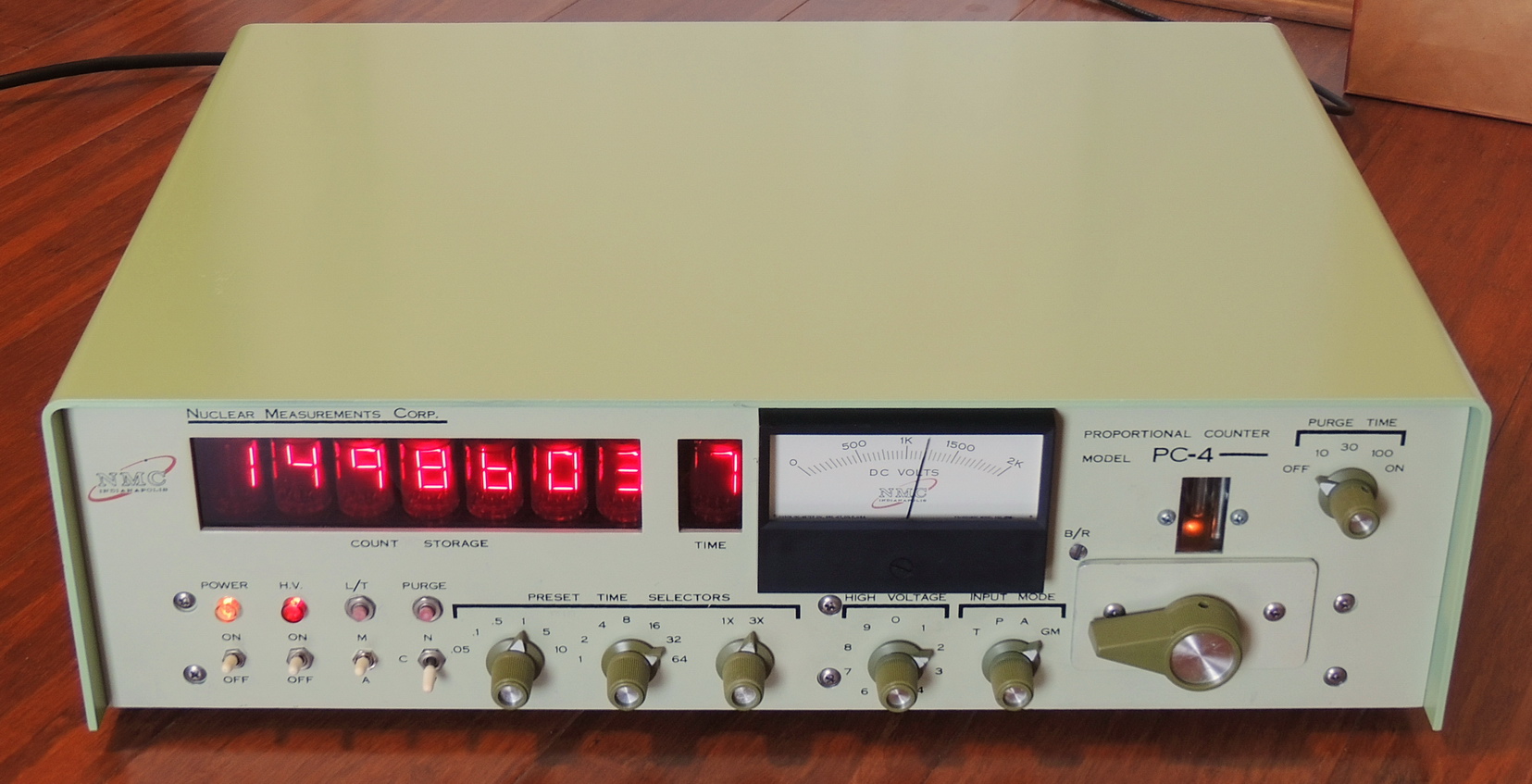
This time I am working on another radiation scaler/counter which is quite a bit different than the last one. This one is a decade newer from 1975 and was built by NMC (Nuclear Measurements Corp.). It has a built-in proportional counter, but has external inputs for Geiger-Mueller, Scintillation, and other sensors.

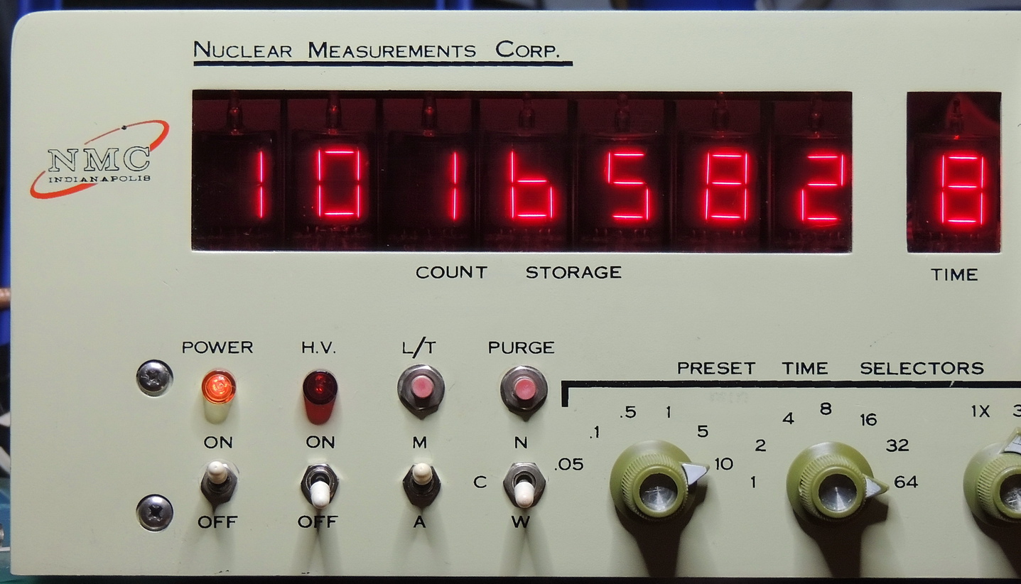
This unit has eight RCA DR2000 Numitron tubes that are used for count and time display sections. This is the first piece of electronics that uses Numitron tubes that I have personally seen or owned, so was quite exited when I discovered them.
The sales pictures didn’t directly show the display, but with some photo enhancements I could tell that there were tube displays which I assumed would be nixie’s.
My original thought in acquiring this unit was that it would be interesting to also have a Nixie tube version of a scaler with seven decades of display verses the five count decades of the Picker Dekatron scaler.
Numitron display tubes are now obsolete but were used in the first half of the 1970’s until LED seven segment displays became popular and affordable. The Numitron display uses incandescent filaments that operate from 3.5 to 5 volts arranged in a seven segment 8 pattern, and some tubes included a decimal point. The filament current for each of the segments is 24 mA @ 4.5 volts, with a total current 168 mA with all segments energized displaying the number 8.
The RCA specified “Mean Life Expectancy” at 95% confidence for the displays is 100,000 hours.
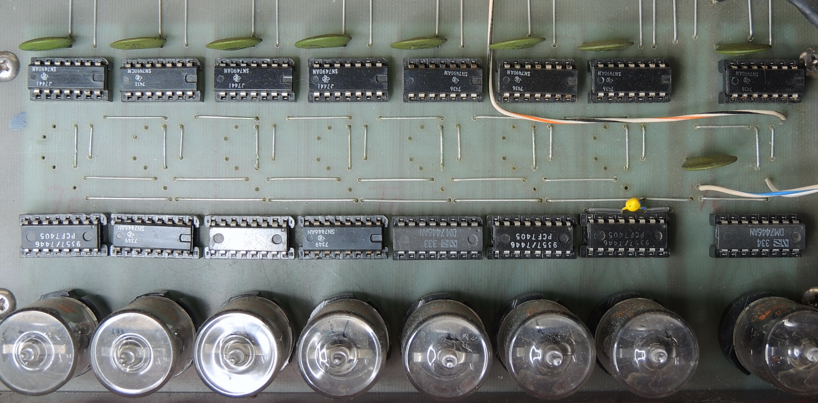
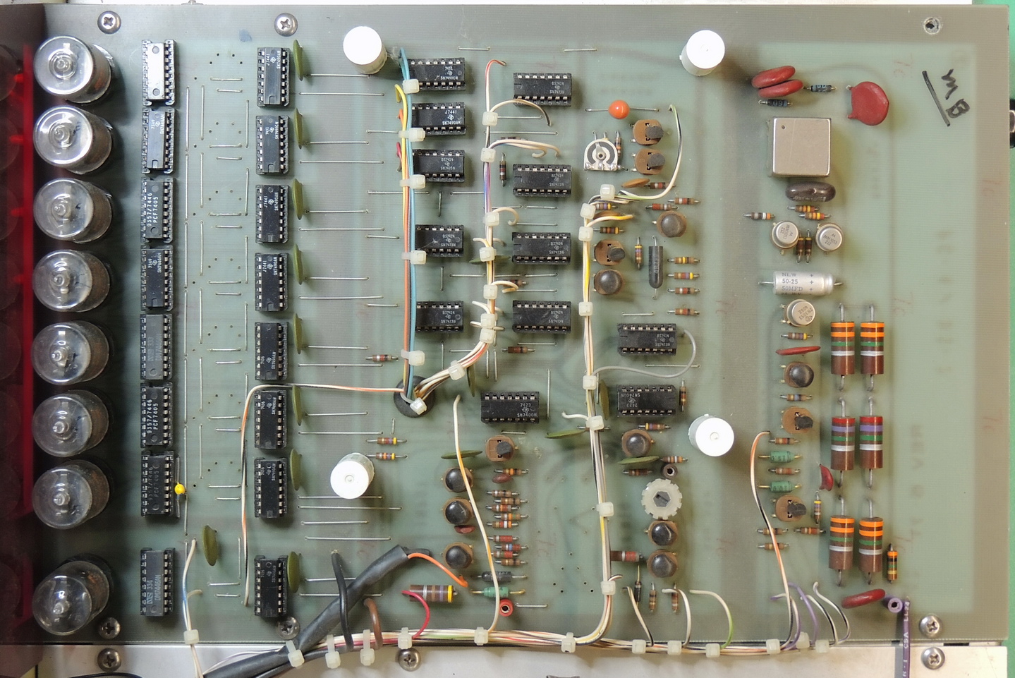
RCA marketed a BCD-to-7-segment display driver CD2501E that could directly drive the filaments of the Numitron display. Then by adding a Texas Instruments SN7490 decade counter IC you have a decade counter.
NMC decided to use a 7446 BCD to 7 segment decoder/driver for some reason, and then cascaded them together to build the 7 decade “Count” display.
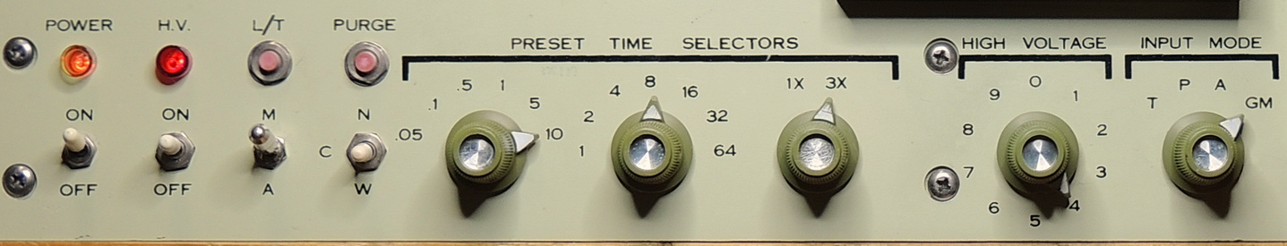
The NMC PC‑4 includes a high-voltage adjustable power supply with a voltage range of 250 to 1,750 volts DC for powering the built in, or external detectors. There is a single adjustment knob on the front panel with a scale numbered 0 thru 9.
There are also three knobs for setting the preset time for the count measurement with a range of 3 seconds to 1,920 minutes (32 hours). Each time selector multiplies the other two time selectors.
There is a main power switch and Neon indicator, and a separate H/V (High-Voltage) power switch and indicator.
The momentary L/T (Light Test) pushbutton energizes all segments of all eight Numitron display tubes to verify proper operation of segments.
The momentary Purge pushbutton initiates a gas purge cycle and then enables the count and time circuitry.
The length of the gas purge is controlled by the “Purge Time” rotary knob and has settings for Off, 10, 30, 100 seconds, and constant On.
The M — A switch selects either Manual or Automatic start of the count cycle.
The N — C — W three-position switch is a bit of a mystery.
The N (Normal?) setting blanks the time during the purge cycle, then starts the time and count after purge completion.
The C (Continue Continuous?) setting continues counting time during the purge cycle, then resets time after the purge ends and begins event counting.
The W (Wait?) setting pauses both the time and event counting.
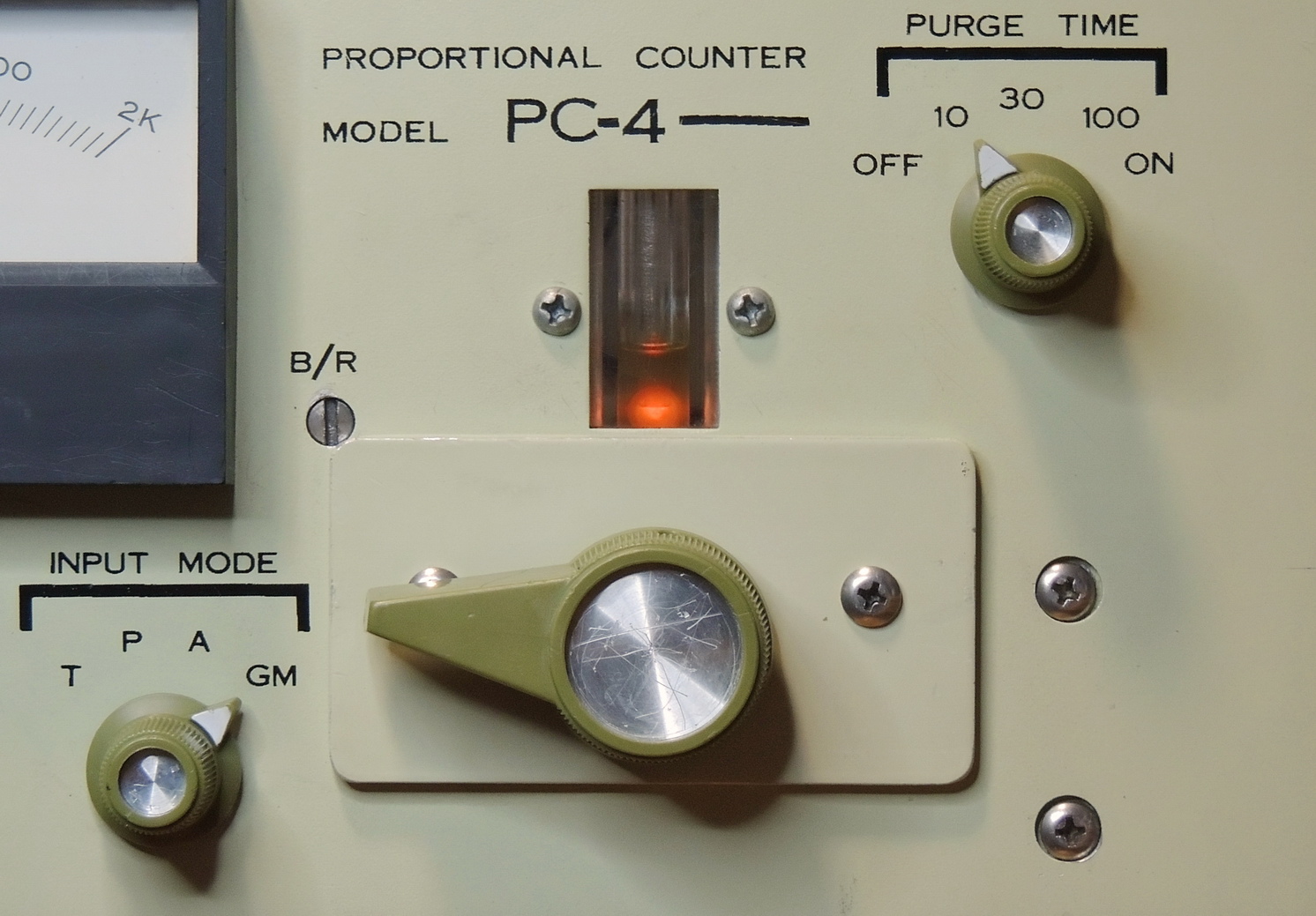
Another front panel control is the “Input Mode”:
T — increments the measurement count from the system clock pulse.
P — selects the internal proportional counter detector.
A — selects the rear panel MS3106A18-8S eight pin connector.
GM — selects the rear panel PL-259 coaxial connector for use with a Geiger–Müller or Scintillation detector.
There are no high-voltage switches involved with the mode selector, only signal switching, so care needs to be taken as high-voltage power is present on all connected devices and unused connectors when enabled.
There is a small shaft with a slot labeled B/R located just above and right of the “Input Mode” switch, this adjusts the bubble-rate of the purge cycle which can be measured in the bubble-counter window just above the proportional detector drawer. There is also another flow adjustment screw located on the rear of the solenoid valve.
That pretty well sums up the tour of operational controls and features of this unit, I guess it’s time to see what actually works and what needs to be repaired. None of the sales photos showed the unit actually powered on. This can be either good or bad in that they realized it might not be safe to plug it in just for a photo, or they did plug it in and the unit was non-working, blew a fuse, or released some magic smoke.
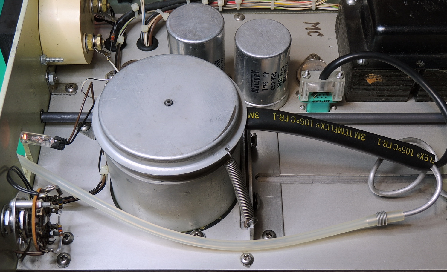
For me as always a thorough visual inspection was performed, then a check of the AC cord, fuse, and transformer primary. For older equipment an important thing to check before applying power are the capacitors.
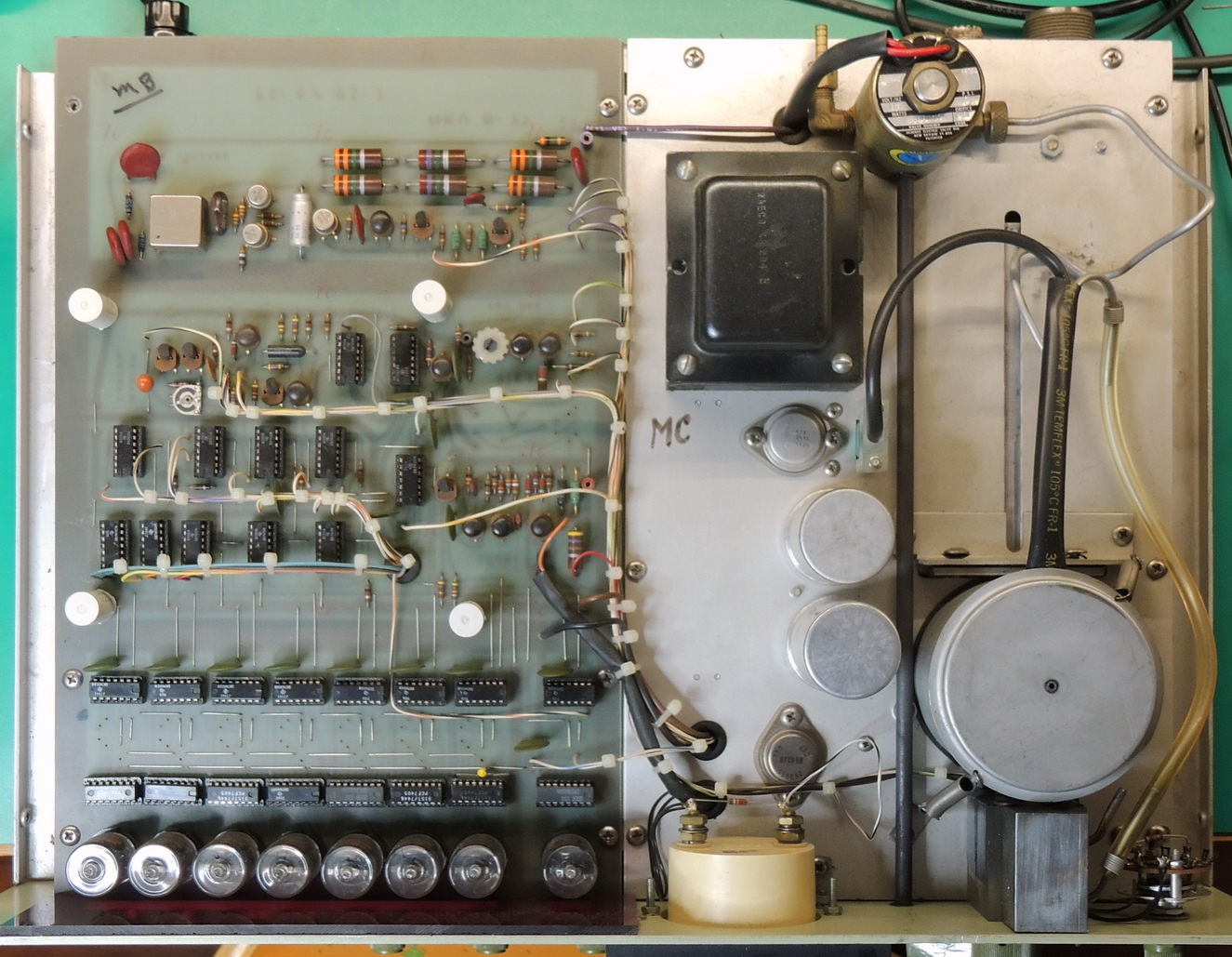
The unit had one slightly bulging electrolytic capacitor on the electronics board, which when removed tested at half the listed capacitance. There were three more radial capacitors of the same value and type, so all four were replaced. All the tantalum and even the chassis mount aluminum can capacitors were in good condition for being 50 years old.
The main circuit board included test jacks for the two power rails so I connected two multimeters to the red and brown test point jacks and chassis ground before the initial power-up. I was fairly certain that the brown test point was the +5 volts as it was connected to all of the 74XX series IC’s. The red test point voltage was an unknown voltage, but was filtered with a 35 volt rated capacitor, so I had an educated guess of what the voltage range would be.
The unit powered-up with no issues and the 5 volt rail was measured at 5.05 volts DC, and the red test point was 23.8 volts DC. I was also presented with my first view of an operational Numitron display as the time counted up from 0 to 9 which then presented me with a loud bang.
Luckily it was only the gas valve solenoid slamming shut at the end of the count cycle. But that did get my heart racing a little bit more than just the excitement of powering the unit up for the first time.
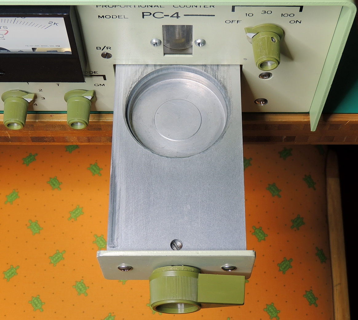
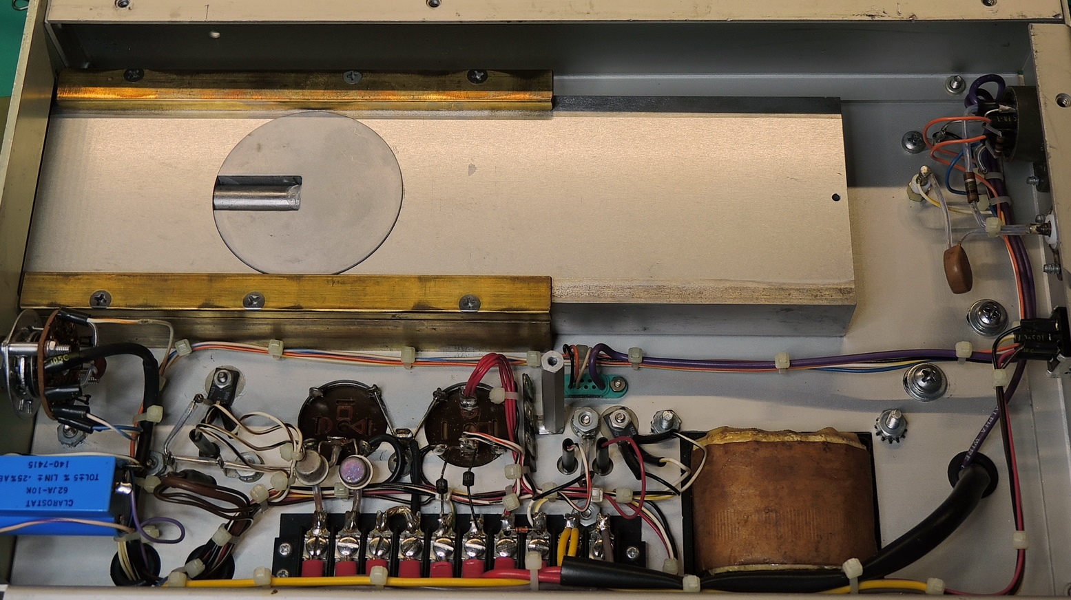
Now that I had verified most of the basic functions were working and many hours of cleaning. I decided to take a closer look at the 2π proportional detector.
I had never seen one of these before so was very curious as to how it was designed and worked. On this unit the sample under test is placed in the cylindrical depression of the drawer, the drawer is closed, and lever is then rotated 180 degrees to seal the sample container to the detector.
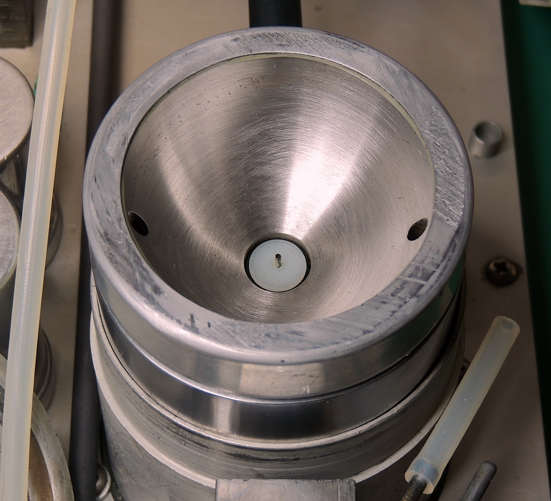
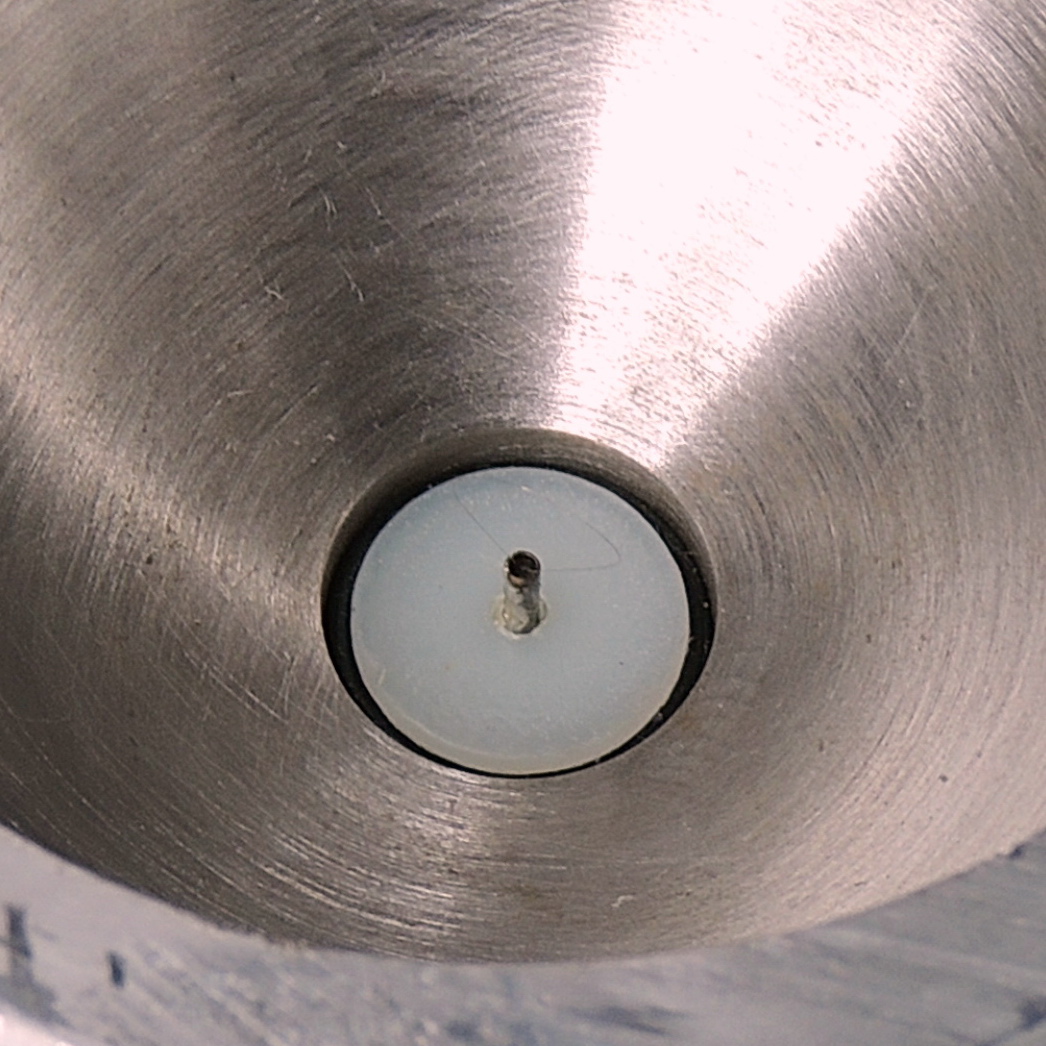
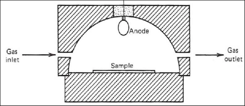
The detector is comprised of a hemispherical chamber with an insulated anode at it’s top center. There are two small holes for the purge gas to flow thru the chamber and the sample is placed on the flat base of the chamber. If you look very close you can see the anode ring wire attached to the center post.
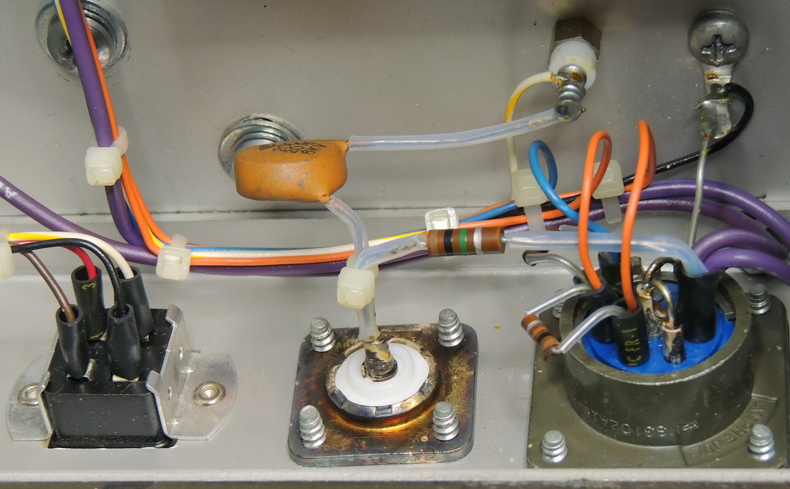
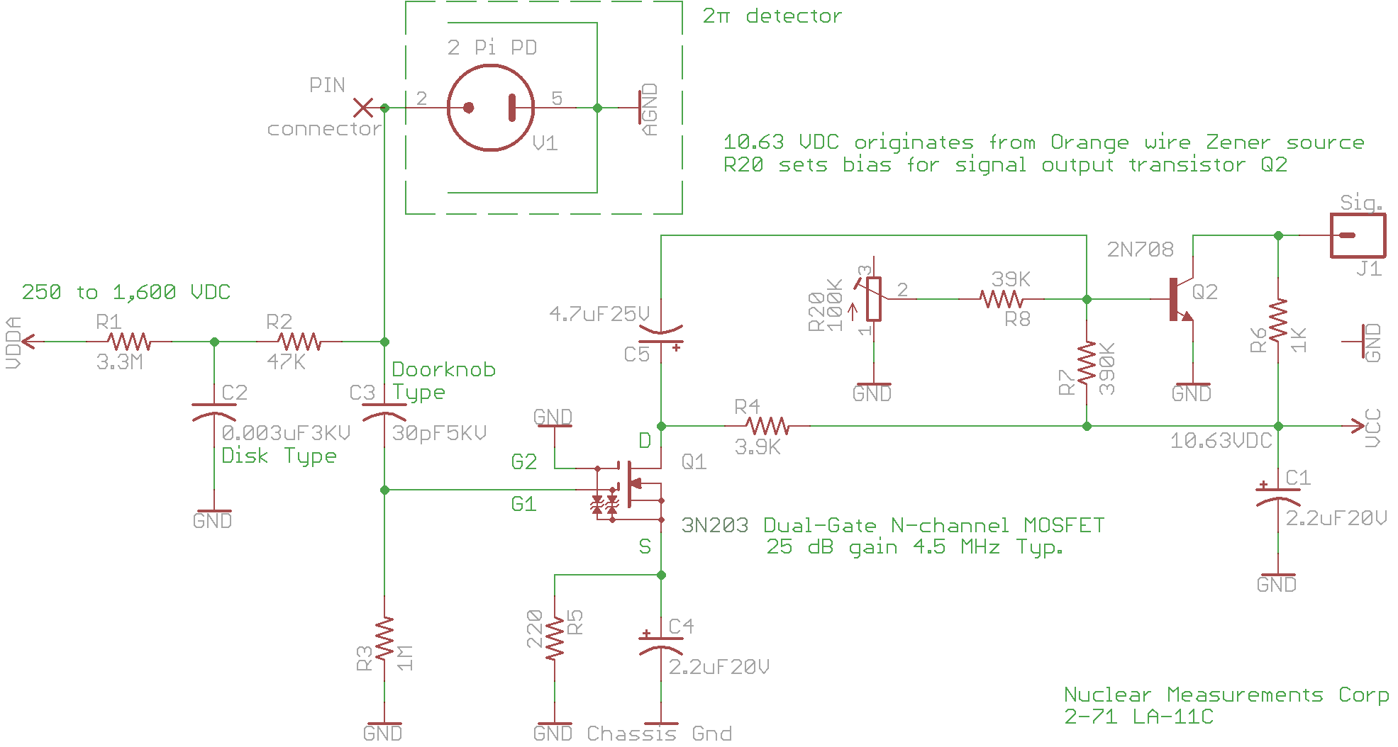
While waiting on some parts to arrive I decided to reverse engineer the preamplifier that is built into the detector.
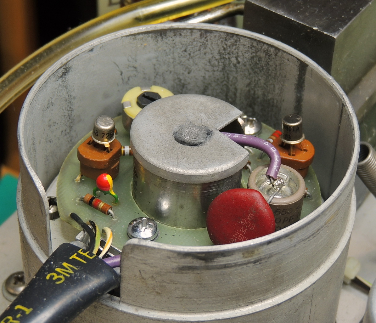
The circuitry didn’t seem too complicated and only had four wires attached. Black is ground, Black/green/white is the 10.6 volt supply, Black/yellow/white is signal out, and Purple is the high-voltage bias. The components are mounted on a doughnut shaped circuit board surrounding the center insulator and chamber anode.
The most interesting component was a 3N203 dual-gate N‑Channel MOSFET with four leads, which I have never come across before.
I did check all the components which were well within specifications, but I do not have any way of testing the detector. This type of detector requires a very specific mixture of purge gas to operate in the proportional detecting range. The required gas is P10 which is a mixture of 90% Argon and 10% Methane. A quick check of my local supplier and the cost is way out of my limited budget.
I do have a homemade scintillation detector that works very well using the GM mode and the rear panel PL-259 coaxial connector.
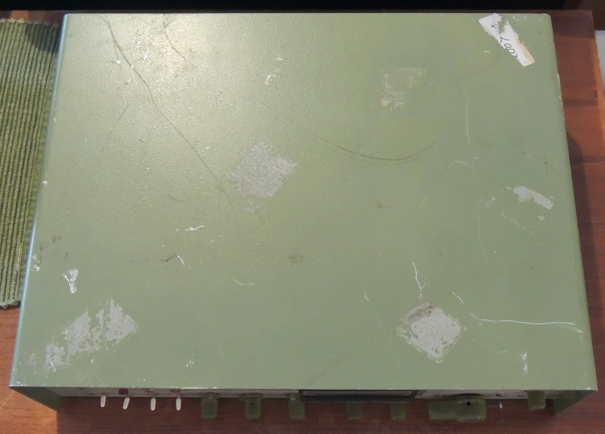
The entire unit was very dirty and required a considerable amount cleaning. The top cover had taken the brunt of it’s past abuse and needed to be cleaned, sanded, and re-painted to be presentable again.
After the initial sanding and cleanup I ended up applying multiple coats of a filler and sand-able primer to fill the deep scratches in the aluminum cover. The cover was then painted using several coats of Krylon colormaxx satin Pistachio paint.
The paint was a great match for the even lighter shade of green of the front panel and darker green knobs in my opinion.
After using the unit for a while I decided that it was worth doing some small upgrades and improvements. The regulated 5 volt supply uses an unregulated supply of 9.2 volts using a 10,000 uF at 10 volt capacitor, which is just a bit too close to the margins for me. It was replaced with a high quality Nichicon long-life capacitor rated at 16 VDC which I was able to mount inside the chassis leaving the original can in place,
The next item was replacing the 10 volt Zener diode and Tantalum capacitor that supplies regulated 10 volts to the proportional counter pre-amplifier board. And while I was at it all the Tantalum capacitors were replaced, along with an electrolytic capacitor in the high-voltage power supply.
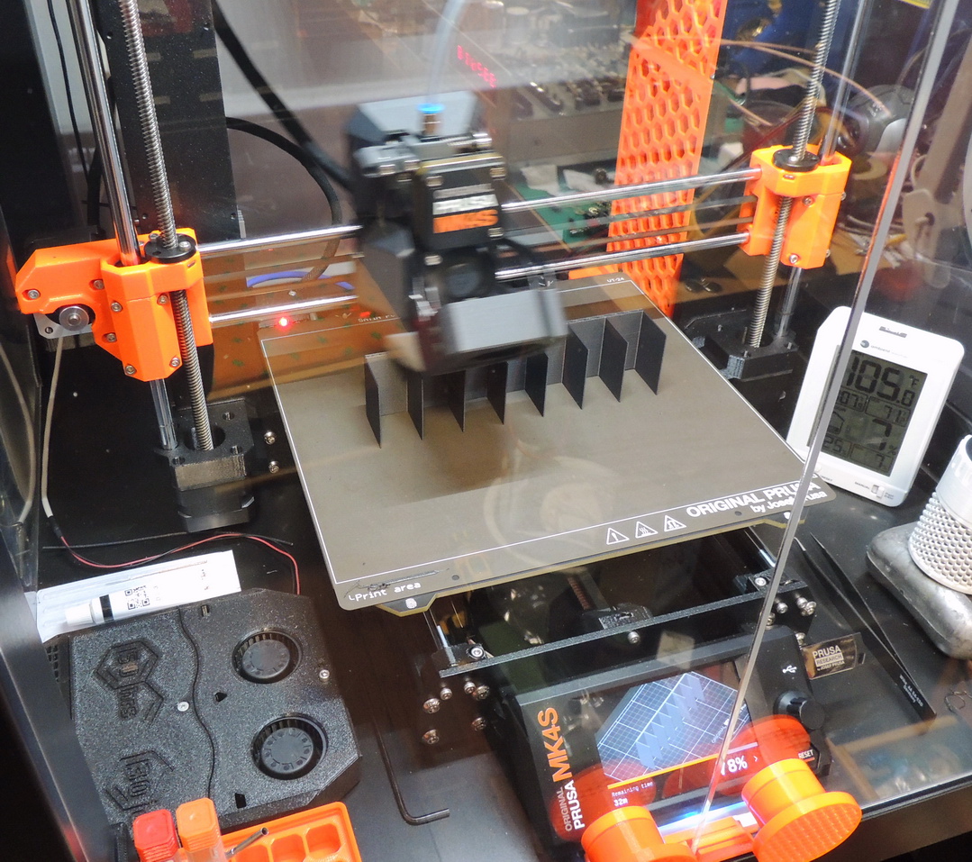
In my research of Numitron tubes I found that RCA offered a tube shield that eliminated reflections from adjacent tubes. It seems that the highly reflective glass tube could produce image artifacts from adjacent tube filaments reducing visibility.
I put together a 3D CAD drawing from measurements of the units display, and after a test prototype I was ready to print a shield using some composite polycarbonate / carbon-fiber filament (PC-CF).
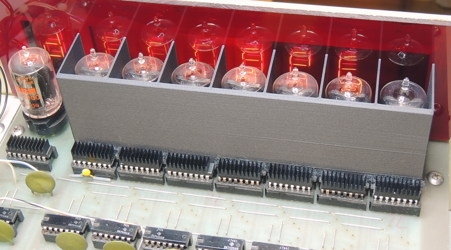
Another item that I decided could benefit from and upgrade were the 7446 BCD to 7 segment decoder/driver IC’s. These IC’s were getting quite warm, greater than 50 degrees C when the lower displays were changing rapidly. I had some DIP style heat-sinks and adhesive thermal material, so all eight 7446 packages were upgraded which should increase their life expectancy.
The PC‑4 has been a fun project to work on, and I have learned a lot during the refurbishment, but it is one of the few projects that is for sale to someone that can utilize it better than me.