

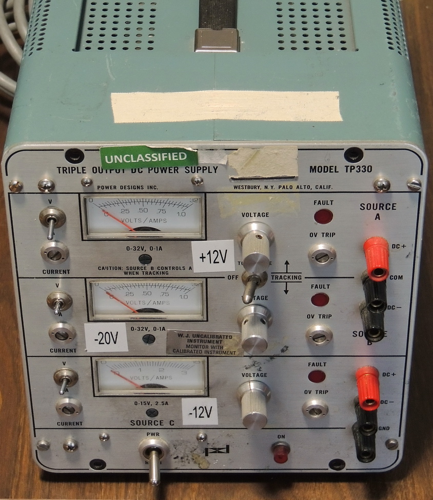
I decided to take a gamble on purchasing a Power Designs Inc. TP330 triple output power supply. It was a bit rough looking with a bunch of stickers on the front panel, but no scrape marks from past sticker removal visible. The seller stated that the bottom analog meter was non-functional, but the output terminals measured voltage that changed with the voltage knob.
I was hoping that the non-working meter was a bad switch or something simple. Oh-Well nothing ventured, nothing gained.
The Power Designs PS330 has two 0 to 32 volt outputs rated at 1 Amp that can be operated separately, or in tracking mode where source A is controlled and tracks the output of source B. The third output is a 0 to 15 Volt at 2.5 Amp non-tracking supply.
All the outputs have a recessed current limit potentiometer along with an overvoltage trip setting potentiometer and fault indicator
The power supply arrived in good condition and was well packed considering it’s size. My first step was to open it up. The outer case is held on with 5 slotted screws, one in the rear and four in the front corners.

Other than being a bit dusty and dirty, the power supply checked out good. All the fuses were the correct value, no visibly damaged components, and all the electrolytic capacitors measured values were good enough for further testing.
Since I really dislike working on dirty equipment, the supply was taken outside for an initial cleaning with compressed air.
Now that the unit was a bit cleaner, it was time to power it up and take a look at the non-functioning meter.
The meter was not moving at all with changes in the lower 15 volt output. I could also see that the meter needle was resting against the dial face, which would definitely keep it from working properly. There was also a varying small voltage on the meter terminals that corresponded to the output terminal voltage changes. So it was time to remove and open up the meter.

All the meters on the TP300 are Jewell / Modutec W‑Series which are a rear mounted style that mount flush with the front panel. These meters use a taut-band movement supported on each end with a flat spring.
The spring on the front of the meter movement had broken its glue bond to the front adjustment support which allowed the back spring to force the needle against the dial plate. A small amount of 5 minute two-part epoxy allowed me to reattach the spring while I kept it under tension until the epoxy cured. The meter was now working again and was reinstalled in the supply for testing.

After load testing the supply, source B and C showed around 0.042 mV of ripple on their outputs while source A was around 0.1 mV of ripple. Source A and B under the same loading should have nearly equal amounts of ripple, which even though is still really low, made me think that the 45 year old capacitors on the source A channel needed to be replaced. Which also led me to believe that the rest of the capacitors may not be too far behind. Another deciding factor for replacing all of the electrolytic capacitors is that it is becoming harder and more expensive to find quality axial style capacitor replacements recently, and in 10 years who knows what the availability will be.

I had most of the capacitors in spares, but needed to order some others and the large chassis mounted 20,000 uF capacitor for the source C, 15V supply output.
While waiting for the capacitor order to arrive I decided to look at the differences of the TP330 and TP325 power supply models.
The only schematics that I have been able to find were for the TP325 model. But when looking at the schematic drawing title block, I noticed that some of the schematic drawings were designated for TP325 / TP330 models.
The TP325 model has the same specifications for source A and B channels, but the source C output is rated as 0 to 6 volts and 0 to 5 amps, while the TP330 has a source C rating of 0 to 15 volts and 0 to 2.5 amps.

The source C control board in the TP330 has a part number of PS-TP325‑8 REV B which lead me to believe that the same board is used for both models with a change of adjustments or components.

I checked all the passive component values from the TP325 parts list against what was actually populated on my TP330 board and found that 7 component values were different. Also capacitor C103 (20,000 uF) which is located on the chassis changed from 15 volts to 30 volts with the same capacitance value.

All of the output transistors are the same for both models which use TRW 1700 C TO‑3 case transistors. Each of the source A and B channels use two transistors per channel which are located on the rear heatsink. The source C channel uses three transistors mounted on left side metal frame.


The rest of the new capacitors had arrived and were installed onto the supply. All except the chassis mount capacitor were replaced with long-life Vishay axial units and the chassis capacitor was replaced with a 22,000 uF 50V Nichicon unit. I also decided to check the Zener diode filtering capacitors which are in the voltage reference sections of the source A and B board as these could also affect output noise on the channels. The four Zener reference capacitors are 6.8 uF @ 35V hermetically sealed Tantalum type units and when checked showed the correct capacitance, but had fairly high ESR values.
I had some “New Old Stock” capacitors that had ESR values around 0.25 Ohms, where the TP330 capacitors ranged from 1.2 to 4.7 Ohms, so I replaced them all.

As I had mentioned back in my HP 3314A Function Generator post, “I have never seen a hermetically sealed version of a Tantalum capacitor fail”, well now I have… sort of?
The specifications for the TP330 are less than 1.0 millivolt P‑P, and my measurement for the source A channel at full load was 0.1 millivolt before the capacitor replacement, which is well within specifications.
After the full capacitor replacement source A dropped to 0.07 mV P‑P, source B at 0.014 mV P‑P, and source C at 0.028 mV P‑P all at full load.
Pretty impressive for a 45 year old power supply, but typically what I now expect for a well engineered Power Designs, Inc. power supply.

