

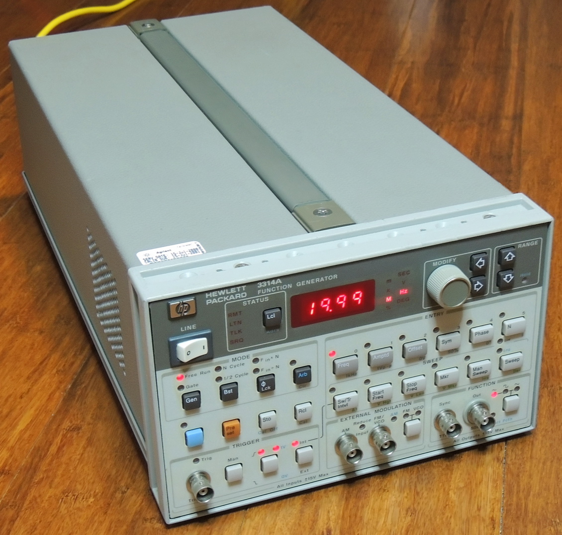
I found a great deal on a Hewlett Packard 3314A 20 MHz function generator that was non-functional, but overall looked to be in good shape. It arrived in great condition and was well packed for a nice change. The seller clearly stated the issues with this unit such as errors when started up cold, which worsened over time until it finally lost the display and LED’s.
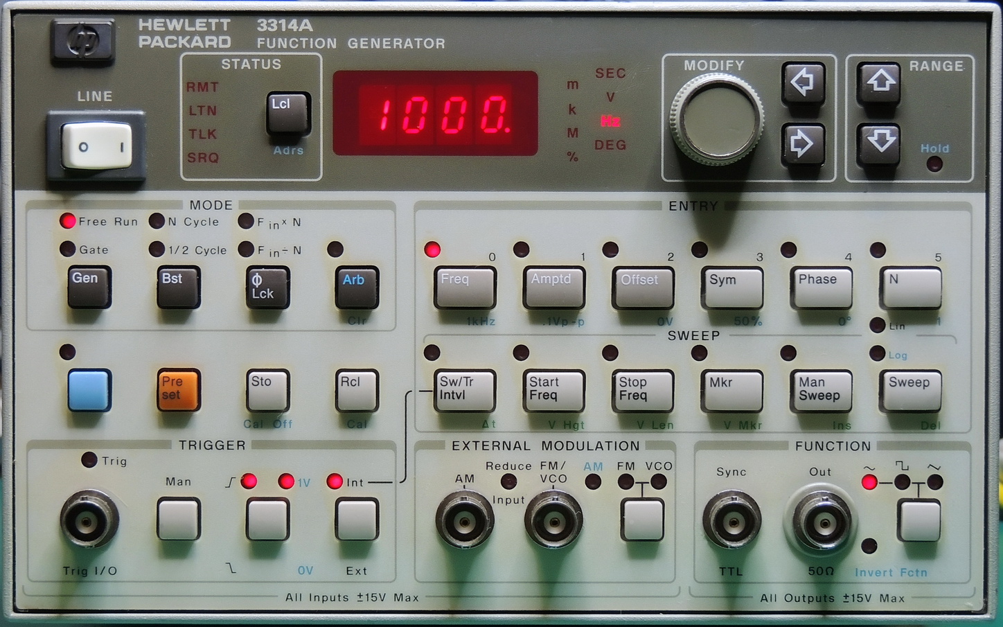
The HP 3314A is a 0.001 Hz to 19.99 MHz function generator with Sine, Triangle, and Squarewave functions along with programmable Arbitrary waveforms. It also is capable of linear and logarithmic sweeps, AM & FM modulation, internal and external triggering.
This unit is a later model with a 2836A serial number prefix and some components dated early 1991. Making it 33 years old as of the writing of this blog. Hewlett Packard made quite a few changes in this revision, some of them good and some not so good.
There are several good YouTube videos out there that show repairs of some common and uncommon issues, especially with the early versions of this function generator. While waiting for my unit to arrive I spent a good amount of time reviewing the videos and downloaded manuals.
As usual my first steps were a thorough inspection and a general cleaning making it easier to work on.
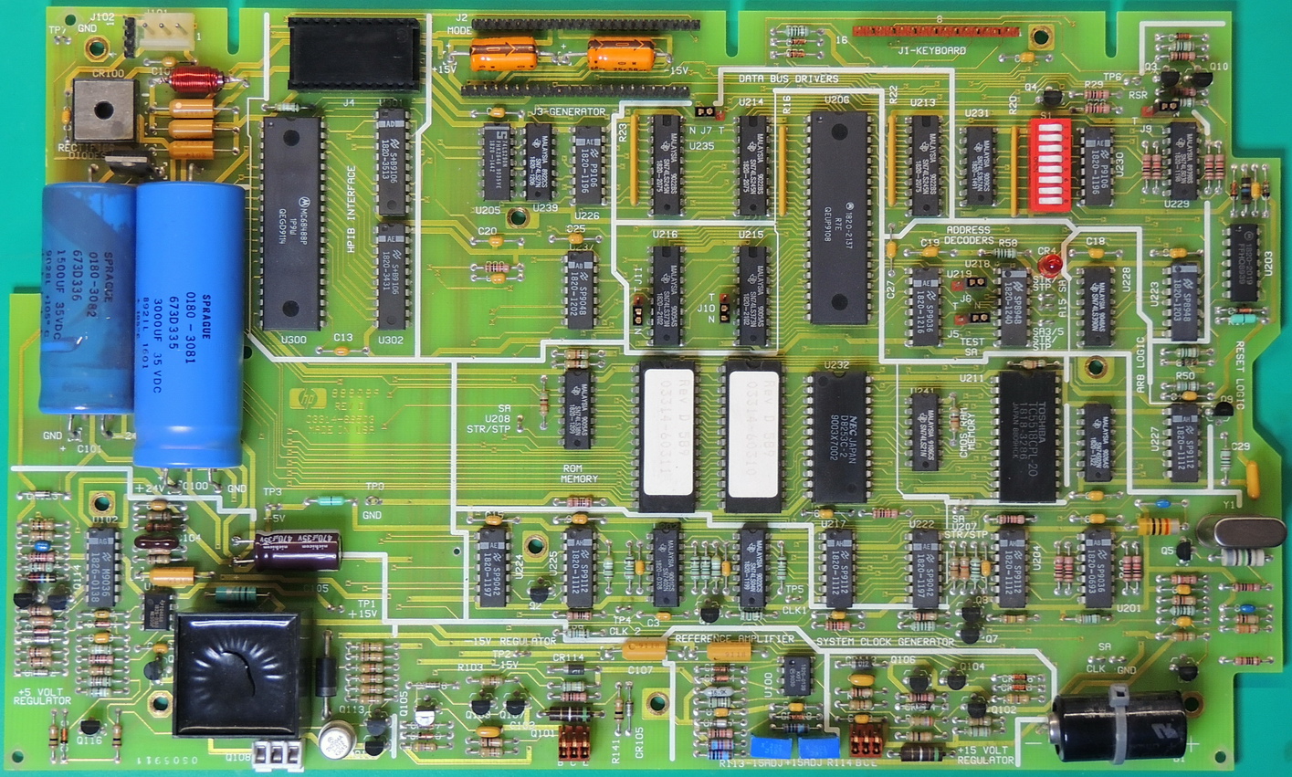
The only visible issue that I saw was a discolored −24 volt circuit filter capacitor which prompted me to check all the electrolytic capacitors which are mainly on the A3 board. The discolored capacitor checked out OK, but the 5 volt output capacitor on the switching regulator tested very bad.
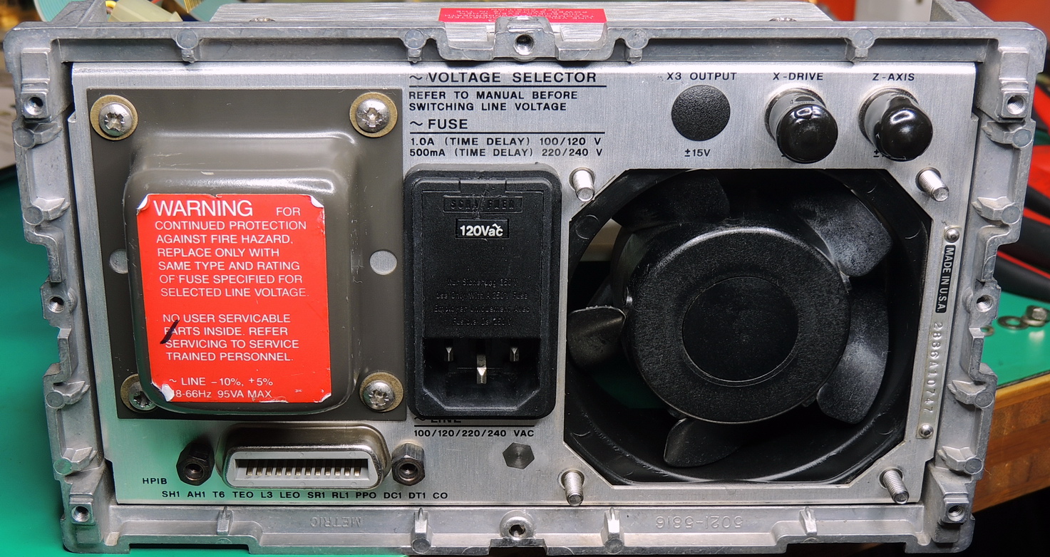
After replacing the 5 volt capacitor and disconnecting the cables to the other boards and front panel, I was almost ready to power it up. But first a quick check of the AC voltage selector switch and fitment of a properly rated fuse was probably prudent.
With several multimeters attached to the three DC voltage outputs I flipped the power switch and all voltages were well within factory specifications.
Next I connected the front panel cable and then re-applied power and was pleasantly surprised with the boot-up countdown display, and then a myriad of error codes which I expected due to the other two main boards being disconnected.
The next step was to start connecting the A2 and A1 boards while continuing to monitor the power supplies on startup.
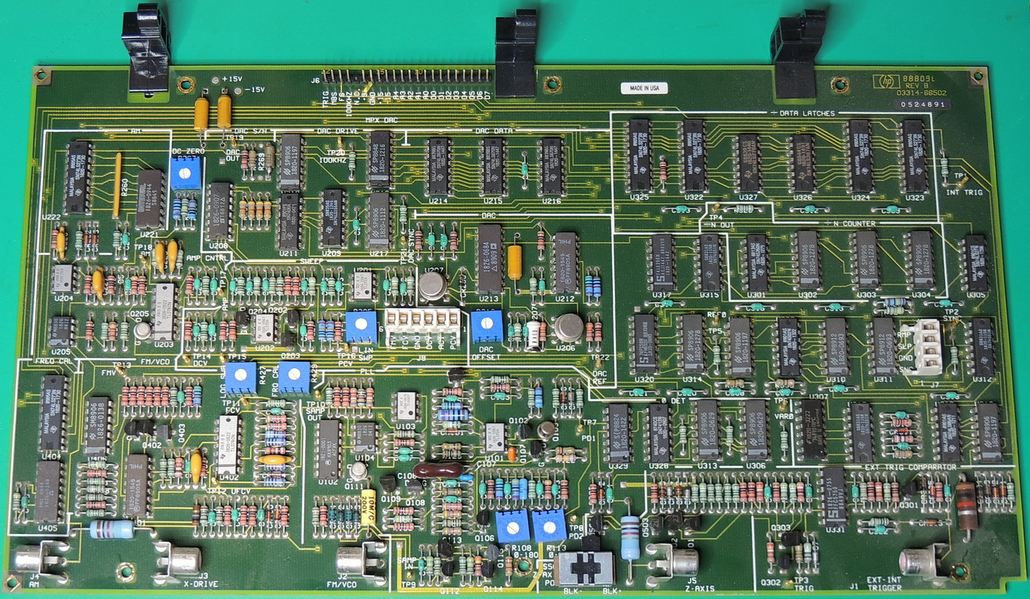
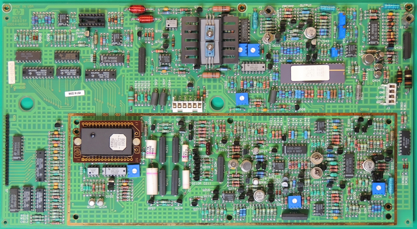
After connecting the A2 board, I no longer had proper voltages on any of the power supplies and of course no front panel display. A quick check of the A2 board’s power rails showed a near zero Ohm short on the +15 and −15 rails and good readings on the 5 volt rail.
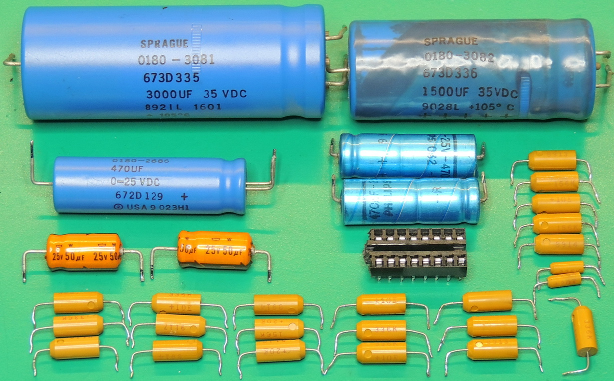
Of course the first suspects were the three molded tantalum capacitors. After un-soldering one leg on each of the capacitors, two of the three were shorted as I suspected.
I just happened to have some hermetically sealed versions of the tantalum capacitors in my spares supply, so I replaced all three.
It seems that in this later revision of the 3314A, Hewlett Packard undertook some cost saving measures specifically replacing the expensive hermetically sealed Tantalum capacitors with a lower cost molded Tantalum version.
So far in all my decades of working on electronics, I have never seen a hermetically sealed version of a Tantalum capacitor fail. But I have replaced dozens upon dozens of the molded Tantalum variants. Then again hermetically sealed Tantalum capacitors are less common, so I should see less failures.
You can probably see where this is going. I must replace all the molded Tantalum capacitors in this unit if I want it to remain operating reliably.
Did I mention that hermetically sealed Tantalum’s are really expensive!
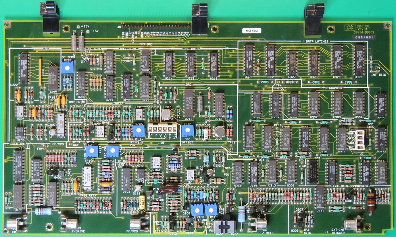
After replacing the Tantalum capacitors on the board, I reconnected the cable to the A2 board and once again powered up the unit. The boot-up countdown was now working again, and all voltages were now in their proper ranges.
After powering down and connecting the A1 board, I was pleasantly surprised to see the boot-up countdown and no errors displayed on the front panel.
A quick connection to my oscilloscope showed proper waveforms and amplitudes for all functions and ranges of this unit.
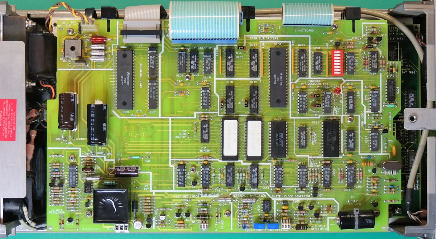
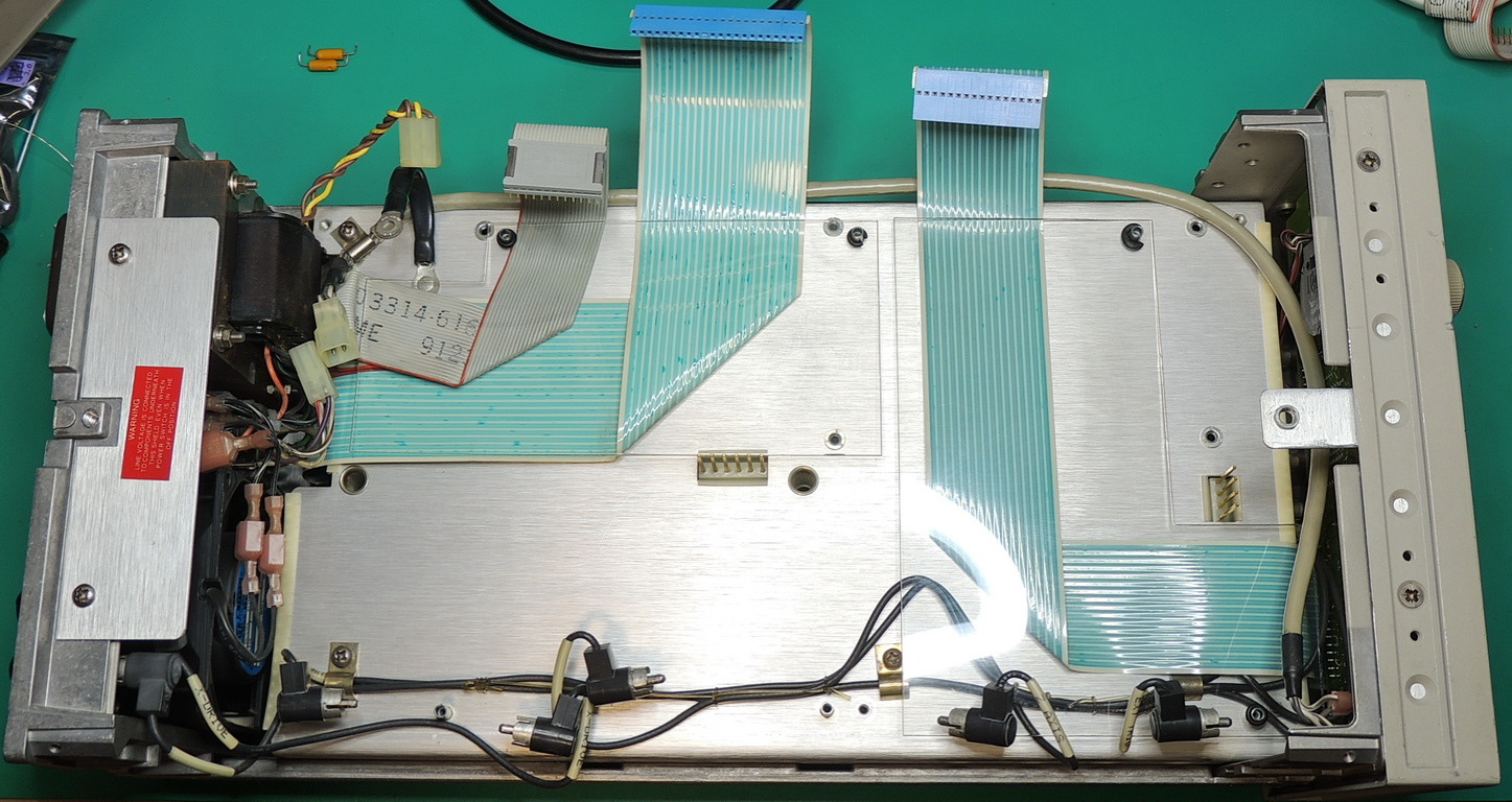
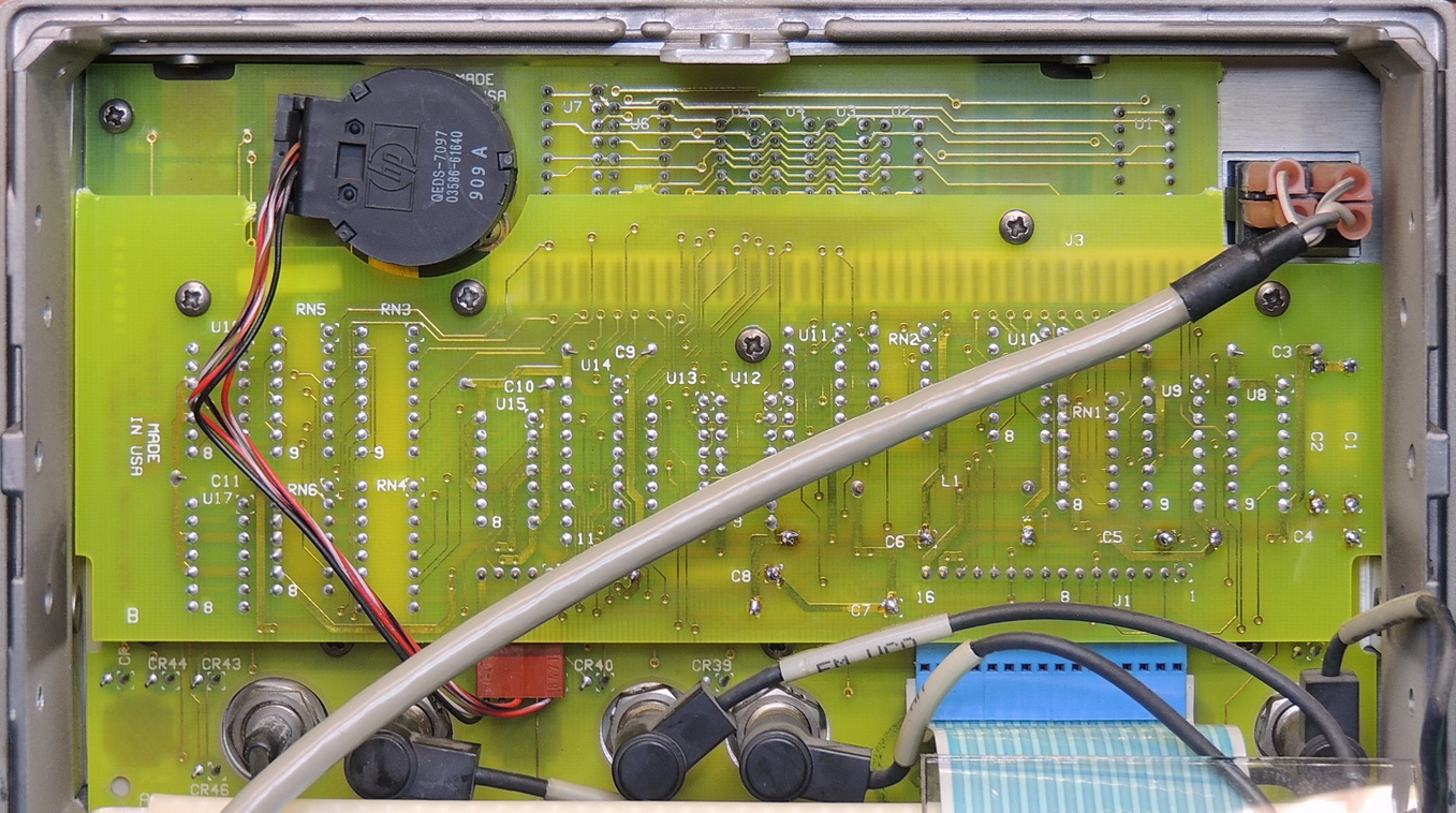
After a parts order had arrived, I replaced all the electrolytic and molded Tantalum capacitors on the A3 board. I had also ordered and replaced the thru-board connectors for the power supply frame mounted transistors, as these have been noted as a point of failure by many people repairing these units. The backup battery tested good at 3.1 volts and showed no signs of leakage so it was left in place.
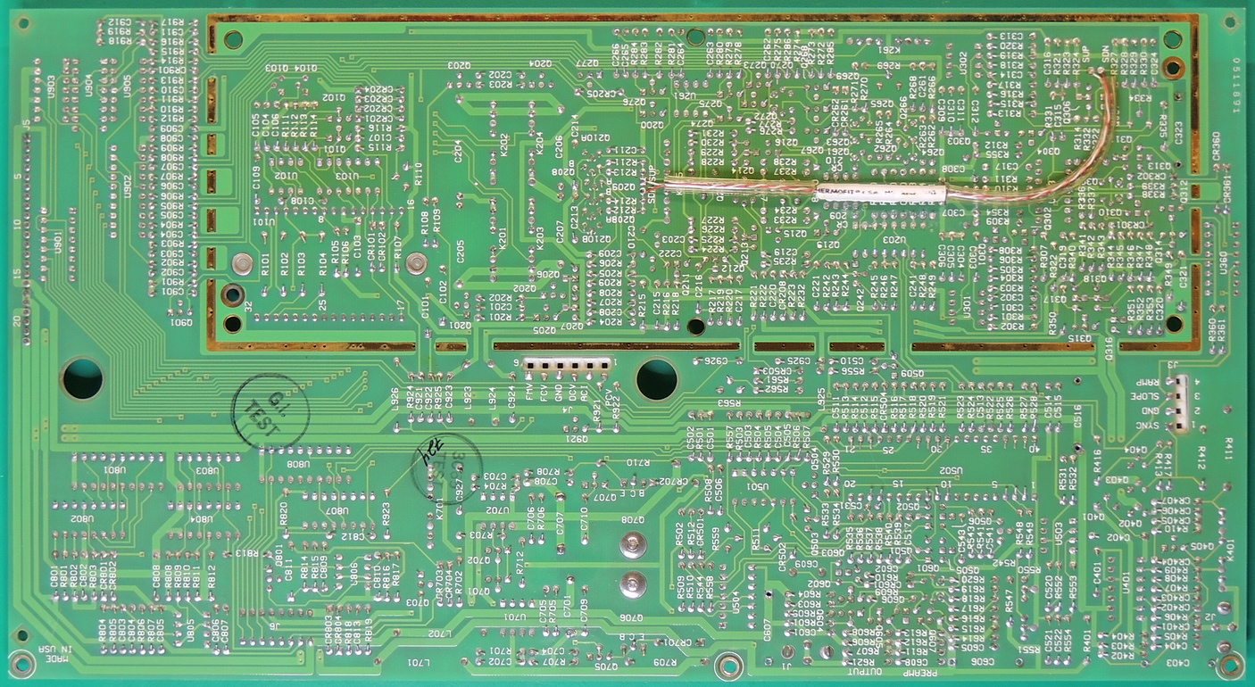
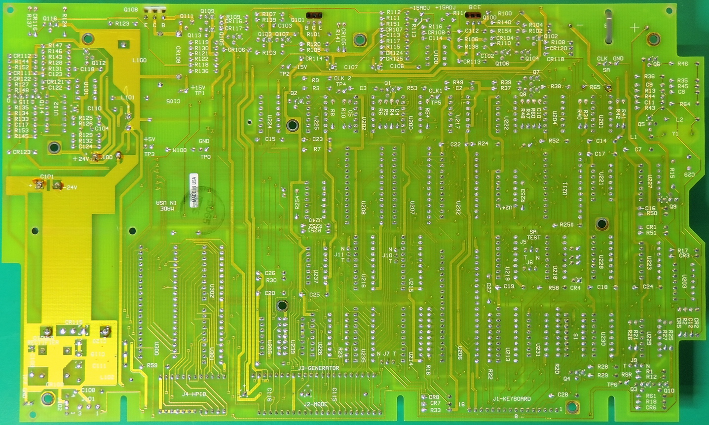
The A1 board needed 7 Tantalum capacitors replaced and I also took the time to clean-up the twisted pair wire jumper on the back of the board. The adhesive had deteriorated over time and left a crusty residue. I used some electronics grade silicone adhesive to reattach the heat shrink tubing which seems to encapsulate some ferrites back to the board.
After replacing all the Tantalum and electrolytic capacitors on the main boards, It was time to tackle the front panel display board.
I had already used up all the hermetically sealed Tantalum capacitors that I had ordered and all of my spares.
A decision had to be made. I could order another $70 plus dollars of capacitors or use some new molded tantalums that I had in spares for the A11 display board.
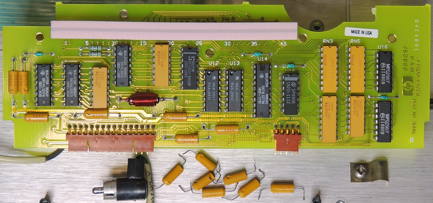
My limited budget won out and all 7 capacitors on the 5 volt rail were replaced with new 39 uF at 10 volt molded Tantalum components. Time will tell if this was a good decision.
This display board revision is an interesting design with all 7 of the capacitors connected in parallel. My guess is that due to height restrictions from the proximity of the A12 board above, it was just easier to use multiple thinner diameter capacitors to achieve the needed 230 uF capacitance with the benefit of a lower total ESR value.
Earlier versions of the (A4) display / keyswitch board used a single board and one large 220 uF at 10V Tantalum capacitor for the 5 volt rail.
There is also a very large pink ZEBRA elastomeric strip connector J3 that connects this board to the A12 LED and key switch board, which wasn’t necessary for the single board (A4).
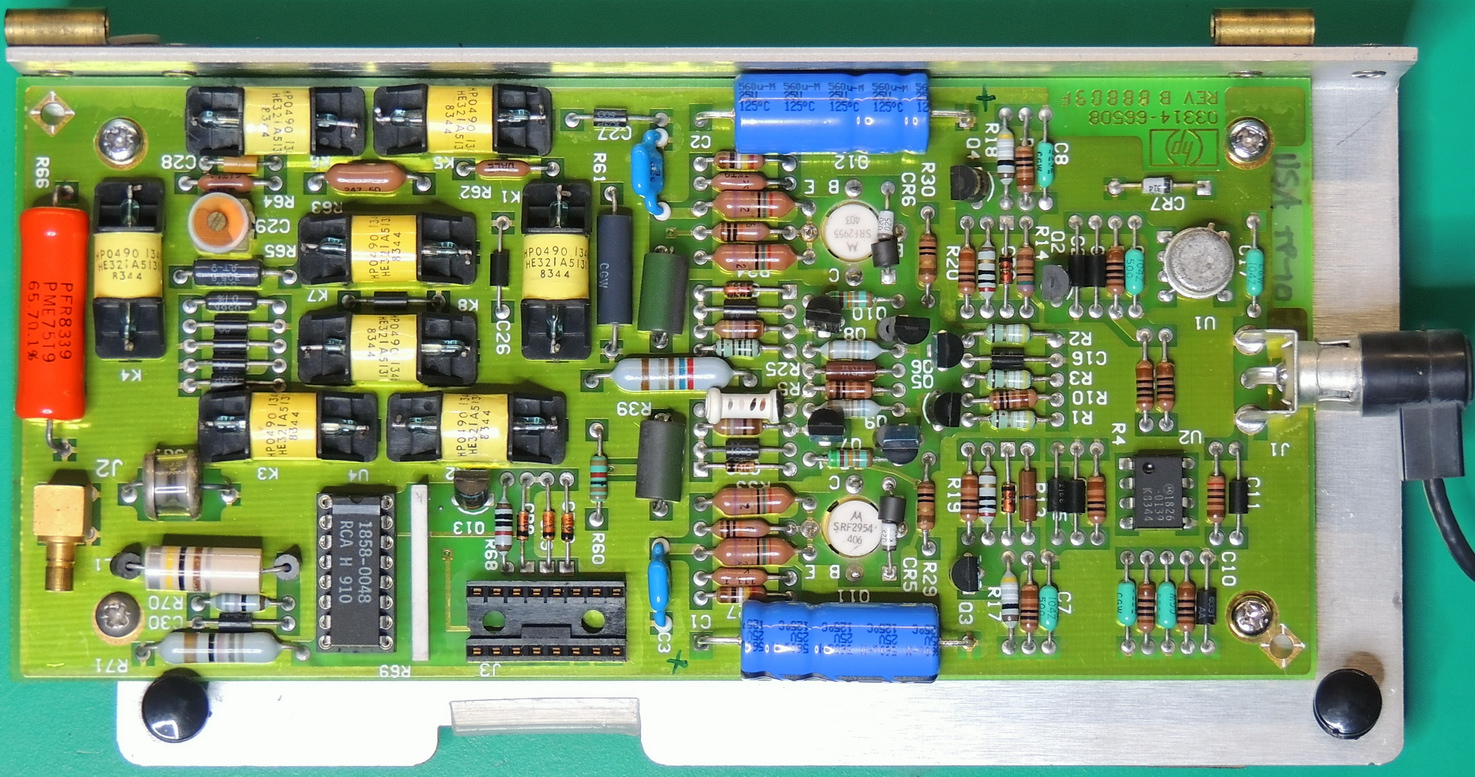
The last board to work on was the A8 output amplifier board which needed to have it’s two electrolytic capacitors replaced, but also had been worked on sometime in the past.
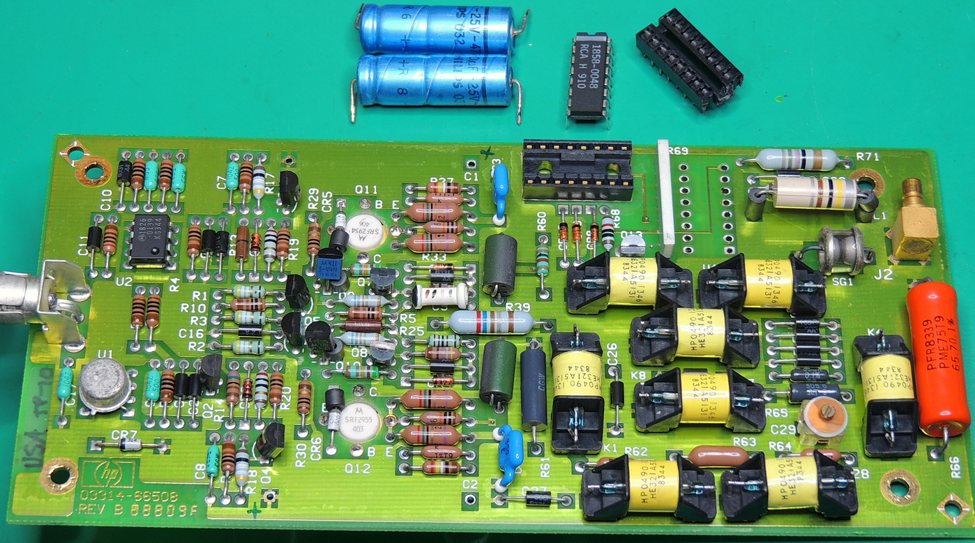
The U4 relay driver IC had been replaced and socketed, but it looks like whoever performed the repair did not have a 16 pin DIP socket so they cut down a cheep larger socket to fit the board with some working but marginal soldering of the socket to the board.
The socket was removed and the board cleaned up before replacing the socket with a quality Mill-Max Beryllium Copper — Gold plated 16 pin socket. The next best thing to directly soldering the IC to the board in my opinion.
After everything was reassembled, I let the unit warm up for 30 minutes then re-adjusted the + & − 15 volt supplies within a few millivolts of 15 volts. The 5 volt rail which uses the +15 supply as a reference was well within specifications. ROM, RAM, and front panel diagnostics were run with no errors, and all buttons worked perfectly.
Most of the performance tests were completed with the exception of tests requiring a spectrum analyzer, due to lack of said analyzer.
All in all this is a great piece of test equipment, and I was again impressed with the quality of engineering and craftmanship that went into designing and fabricating this unit with a few small exceptions (molded Tantalums). Although in the early 1980’s the price of Tantalum increased dramatically which may have prompted the cost savings.
Hi was wondering if you could help could you give me the part number a the hermically seal tantulum capacitors you used.
Hi Paul,
I actually replaced several different values of sealed tantalums in the repair.
The most common was the 15 uF @ 20 VDC units.
They were replaced with Vishay Sprague M39003/01–2289 DigiKey # M39003/01–2289SP-ND
The Vishay Sprague units are slightly more expensive than the Kemet brand but in my opinion worth it.
I try to stay with the CSR13 series as they are a good value between cost and quality.
Good luck with your project,
Greg(Barbouri)
Thanks mate i was struggling to find them as ive never replaced tantalums before and this is the futst instrument repair I had to make. I too had issues with the rail voltages and changed yhrm on the power supply board. Got correct rail voltages. Connected the display and it ran through the count down, with usual errors like yours as the other boards were not connected. After connecting the the ‑15 and +15 rails were right out of spec. Following you wonderful article thats what had led me down the tantalum path. Cheers for the help…
I teplaced the tantalums on the A2 board, when I hv it unplugged i get a display count down to errors. When I plug in A2 board the mode cable i get a display count down then errors, however when i then plug in the generator cable I get no display… do you hv any ideas as ive come to a dead end.