

Repairing and clean-up of a Hewlett Packard (HP)5300B Measuring System with a 5305B 1,300 MHz Counter module.
This was supposed to be just a clean-up project, but this one turned into a bit more work that I had expected.

This HP 5300B system was purchased on Ebay as “powers on, the numbers display on the screen”. When it arrived I plugged it into my Watts Up? power monitor and turned it on. Nothing happened, there was no display and the power monitor showed .000 amps.
The seller did make it right by refunding part of the purchase, so now it was a challenge to see if I could get this unit working again.

To start with the fuseholder cap was not the original and was intermittently making connection. After replacing the cap, I had AC line voltage to the transformer and low voltage AC to the board. I noticed on further inspection that the transformer aluminum support was severely deformed, which was also causing bending of the circuit board and an attached power transistor using the aluminum frame as a heatsink.

After a hour of disassembly, straightening, and reassembly it was time to try powering up the unit again.
Still no display or DC system voltages.
After a bit more troubleshooting the problem ended up being a damaged contact on the 50 pin Centronics style connector that mates to the different plug-on modules for the system. Pin 25 DC +22 volt power is connected via the plug-on module to pin 50 (DC-IN) which then is switched by the front panel power switch, and then is converted to system voltages. This allows the system to utilize a battery pack between the plug-on modules for portable operation.
Most likely the damage happened at the same time the aluminum frame was deformed by a severe drop causing the transformer to move things around inside the case. This was not caused by the most recent shipping to my location, as I also found three of the four plastic board mounting latches damaged with missing latches, but no remains of the latches inside the case when opened.


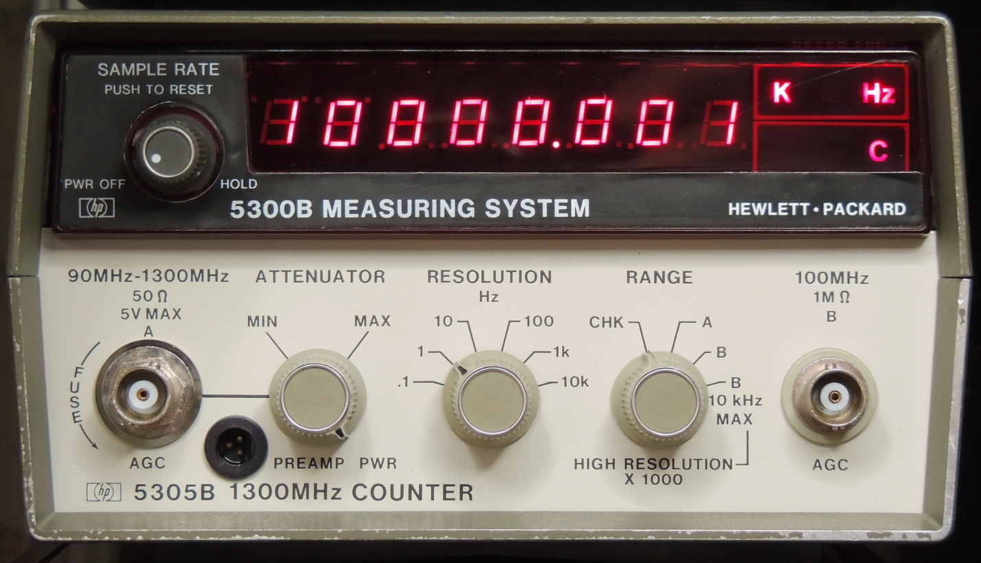
Now that the unit was working, it was time to perform a through cleaning and take some photos of the 5305B 1,300 MHz Counter plug-on module.


The Hewlett Packard 5305B is a beautiful example of quality engineering from the mid 70’s by the design team at HP. This unit was built in late 1981.
I still need to check the calibration of the 10.000 MHz oscillator, but currently do not have anything accurate enough to do the job.
Hmmm, sounds like another future project!
Thanks for sharing Barbouri.
It is indeed a very nice looking piece of test equipment.
Cheers,
Tim
Beautiful pictures of the instrument. I am pleased to use such an instrument with optional TCXO. Regards Ferenc, YU7BX
Hi,
I have a 5305B with similar problem of no or garbled display on 7segment leds. The unit used to make a sharp buzzing noise when working, but eversince the noise has gone the display is gone too.
Pls suggest possible repair tips.
Thanks !
Salman
Hi Salman,
Most likely there was a problem with bad capacitors in the power converter section.
The +22 volt supply is converted to AC and is then rectified and filtered to make the system voltages +5, ‑5, +17, ‑17, and +3.5V.
The shorted or faulty capacitor causes excessive current draw in the converter and can make humming or buzzing noises.
I would suspect that the noise stopping is related to a diode, power transistor, or transformer (-3011, ‑3012) failing due to the excessive current.
Usually there will be visual signs of overheating of the failed component.
Greg (Barbouri)