

Restoring a Power Designs Inc. 6150 power supply
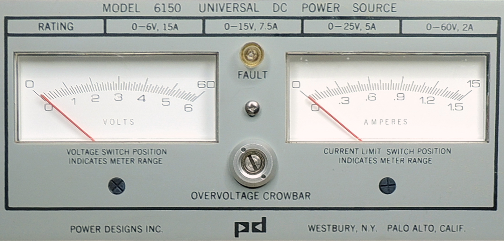


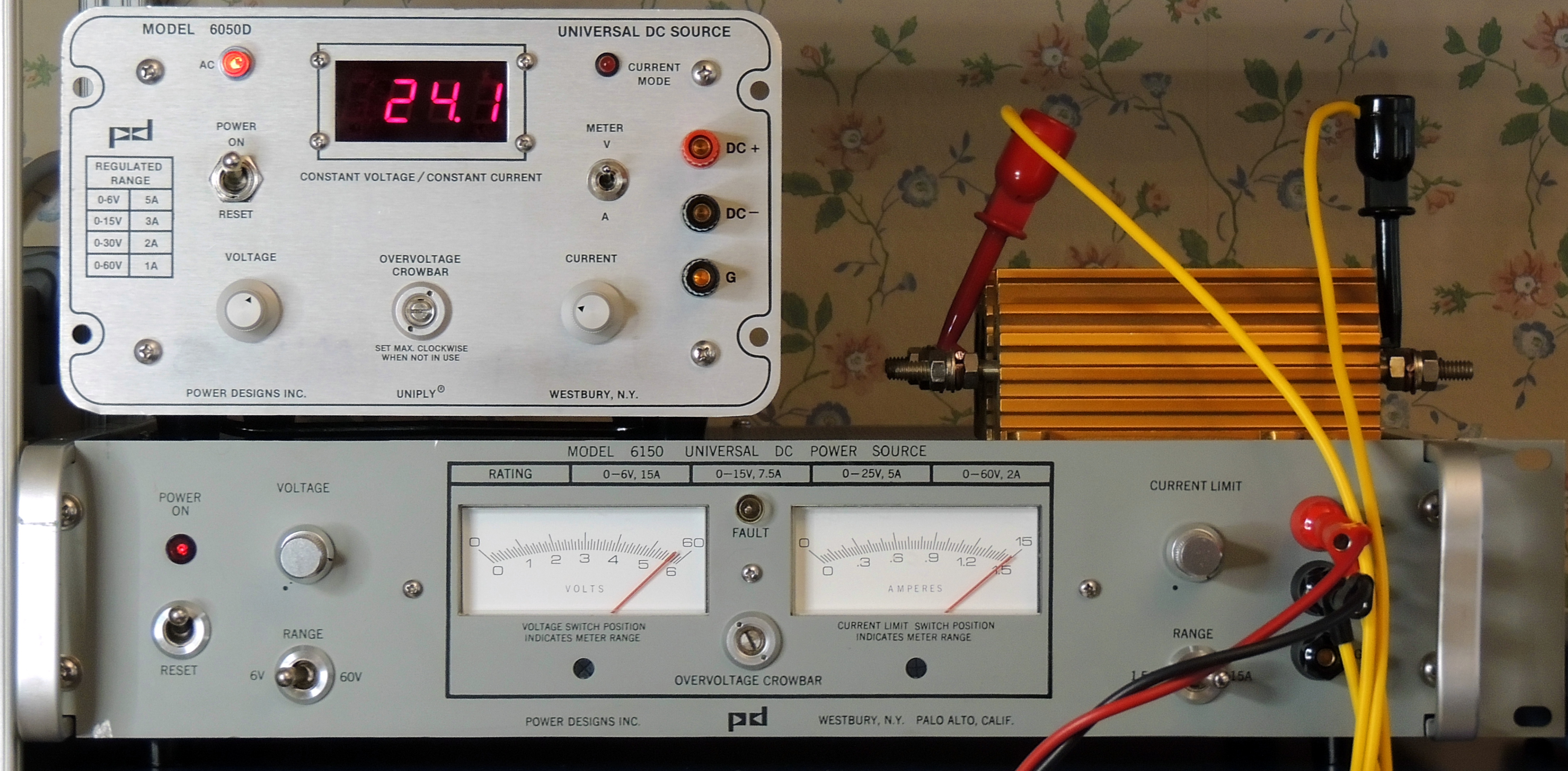
The Power Designs Inc. 6150 power supply is the highest wattage unit in the low voltage single output series. It is a linear power supply designed to output 0 to 60 volts DC in 4 decreasing amperage ranges from 15 to 2 amps as the voltage is increased.
It uses the Power Designs UNIPLY® circuit design (Patent #3,699,352) to accomplish this.
It utilizes dual meters for output voltage and amperage with dual ranges for each meter. The voltage and current limit controls are single turn wire wound potentiometers that also change range settings with the associated meter range switches.
The power supply was a bit dusty inside, but not nearly as bad as several units that I have worked on in the past. I was able to find all the loose hardware inside the enclosure with the exception of one nut. I was worried that a stud mounted diode had possibly been damaged by the loose 110,000 uF 16 volt electrolytic capacitor. But it and the capacitor checked out good.

Most of the restoration involved cleaning and mechanical repairs. I did end up replacing the 15 volt section electrolytic capacitor, but surprisingly the loose 6 volt section capacitor tested good. I will still end up replacing it when I make my next big parts order.


All the electrolytic capacitors on the main board looked great and tested fine in-circuit. I still haven’t decided if there is a need to replace them yet. I am still trying to figure out the manufacture date for this unit, so far my best guess for this units vintage is 1984.

Power Designs 6150 front panel On set to 3.3 volts on 6 volt range with no load
Under full load at the upper voltage in each of the 4 ranges, voltage regulation was better than 0.002% and voltage ripple-noise was less than 0.16 mV P‑P. Current noise was less than 2 mA at a 3 amp load.
I have not yet found an online service manual for this power supply, so I do not know the design specifications. Drop me a comment if you know where I can find one.
I decided to photograph this unit extensively since there was not much in the way of photos and documentation available.
More photos: (click on photo to view at full resolution)


Power Designs 6150 Instruction Manual with Schematics
courtesy of “gto 4ben”
I have a Power Designs 6150 (no manual nor schematic) and resistor R48 on the main board burned. Would you please ohm out R48 and R47 and send me the values. I still need to figure out why R49 smoked, but the lack of a schematic is hindering me.
Thanks
Hi Edward,
Resistor R48 is 0.75 ohms, and R47 is 0.216 ohms according to what is actually printed on them.
Also printed on both resistors “PD305” and “411”.
Both resistors connect to R46, which i believe is the large resistor just behind the front panel. Possibly the main current sense? and these two resistors are possibly for the 1.5 amp and 15 amp ranges?
I doubt that I would get a valid resistance reading on them in-circuit without removing a lead anyway.
Greg (Barbouri)
Hi Greg,
On second thought, would you mind ohming out R47 & R48 in-circuit? If they really are that low of a resistance, whatever is in parallel with them won’t make that much difference.
Thanks,
Edward
In circuit resistance checks with Range switch set to 15A.
R48 = 0.058 ohms (labeled value 0.75)
R47 = 0.134 ohms (labeled value 0.216)
R46 = 0.033 ohms, 25 watts
Cable resistance from “TO R46‑2” to R46 terminal = 0.0140
Greg (Barbouri)
Thanks, Greg!
Hi Greg,
Thanks for the information concerning the resistors. My problem with the unit is in the constant current section, but I do not know if I can troubleshoot it without a schematic.
Sincerely,
Edward Eison
Your unit is very clean! I’m happy you got it working. Thank you for all your photos.
I also have a PD 6150. I just finished troubleshooting it. First problem was that the power switch did not turn off due to stuck contacts. The second was that the output voltage does not go above 3.125V at 0A on the 6V range. It also triggered a high current on the meter with no load at >19V on the 60V range. Once triggered, it immediately settles back and repeats unless I lower the output voltage below 19V.
After replacing the power switch S1, I discovered C19 & C20, 1000uF, 70V, output caps were faulty (6 ohms across) and the C3, 60uF, 75V cap that filters the power for the reference section was open resulting in only 20V across it instead of 53.5V. A loss of reference voltage downstream would explain the low output voltage range. Replacing C3 restored operation.
To celebrate my good fortune, I’d like to offer a scanned manual with schematic if you or your readers are still interested.
Hi gto4ben,
Congratulations on getting your PD 6150 up and running. I ended up replacing all electrolytic filter caps on my unit.
I am sure that many of us would love to have a scanned copy of the manual. I still need to calibrate the current meter on mine, but am unsure which pots to adjust.
Thanks,
Greg(Barbouri)
Hi Greg,
Great blog, I just dug my 6150 out of its hiding place and although it basically works, it hasn’t been serviced in at least 17 years and possibly a lot more!
I’m not sure how to email gto4ben To ask for a copy of the manual and schematic, is there a way I can see his email on the blog?
Alternatively I’m happy for you to pass my email to him!
Many thanks, Dennis
Hi Dennis,
There is a link to the PDF file at the end of the blog, just before the comments.
Greg (Barbouri)
Consider using the “Buy me a coffee” link. Thanks!
Doh, I missed the obvious! Thanks Greg, enjoy the coffee 🙂
Hi Dennis,
Thanks for the Coffee!
gto4ben also annotated the the adjustments on the schematic page with notes on what the adjustments perform.
Greg (Barbouri)
Thanks for uploading the manual, it’s essential!
I have been using my long neglected 6150 as a 12v source to test my equally ancient and neglected radio equipment
I was plannnig to refurb the 6150 but after a cursory clean on the outside, I tried it and it seemed to be working ok. After a few days I noticed it was getting very warm and there was a loud 50hz hum, and the ammeter showed several amps when the load was drawing a few hundred milliamps.
I removed the covers today and found it was caked in dirt and had obviously suffered from damp where it was stored so step 1, a google clear and careful wipe down of the board and other components with alcohol.
Same fault exists and I suspected that the output board could be the problem with old cap’s, but I haven’t checked those out yet.
The symptoms seem similar to those you described — pulls high current with no load, I get about 9v on the 60v range and about 3v on the 6v range.
I suspected C19/C20 but hadn’t got back to C3 yet so I’ll replace all 3 anyway as well as it seems likely we have the same fault!
R49 is rusty and stuck, but I can’t see that affecting the output, just he meter reading. All the other pot’s have been replaced with plastic bodied ones at some time in the past.
Thanks for posting this, it helps to have a comparison!
If you send me an email to the email address I provided here to comment, I’ll gladly respond & attach a copy of the manual (pdf 2.5MB size)
For current adjustment, this is what I did.
1st, set the current range pots (1.5A-R49, 15A-R32) for each respective range to 10% over rating.
2nd, set the panel current meter pot R57 for one of the ranges to cal the current. 15A will heat the load causing the resistance to change (unless you have an electronic load) and may make a constant 15A difficult to attain so I calibrated the meter using the 1.5A range which will be good enough for the 15A range.
This is my interpretation of all the pot adjustments based on both the 6050 and 6150 manuals:
R23-Voltage Max for flashing limit lamp. Set up to 2V above max performance rating (62V).
R32-Current Max 2 (15A) for front panel flashing limit lamp. Set to 10% above max performance rating. (16.5A)
R34-Front Panel Voltage Limit Control
R39-Front Panel Current Limit Control
R57-Panel current meter Cal
R49-Current Max 1 (1.5A) for front panel flashing limit lamp. Set to 10% above max performance rating. (1.65A)
My voltage panel meter lost the grey mechanical zero adjustment in the front that you use a screwdriver to zero the pointer when off. Would you know where I can get a replacement, perhaps from a broken meter?
Great stuff as always. I recently acquired a Power Designs 6150. I haven’t fully cleaned it up but it’s largely in working order.
Mine appears to be a slightly different vintage than yours with several smaller trimmers.
https://imgur.com/a/xb9aVpi
Hello good afternoon.
I have this beautiful power DC source.
I was using it with a car stereo and by an accident my child turn up the knob to high and it burn my stereo also this unit is not working, well it turn on but it’s not working properly, I know that may something is burn out but it doesn’t looks nothing burn out.
Can you guys give a hand how to fix this beautiful DC power source
Thanks o much for who can help me.
Hi Enriquez,
The 6150 has several built in protections from overcurrent.
The first thing to check is the two fuses on the back panel (20 amp and 5 amp).
Greg (Barbouri)
Hello Greg
Yes I did check the fuses and both are ok but still turn on but is not working like before.
Thank you Greg.