


Quick Projects Update
Way too many projects and too little time. Luckily I had a few days off from work to make a bit of progress on several existing projects, and to start some new ones.
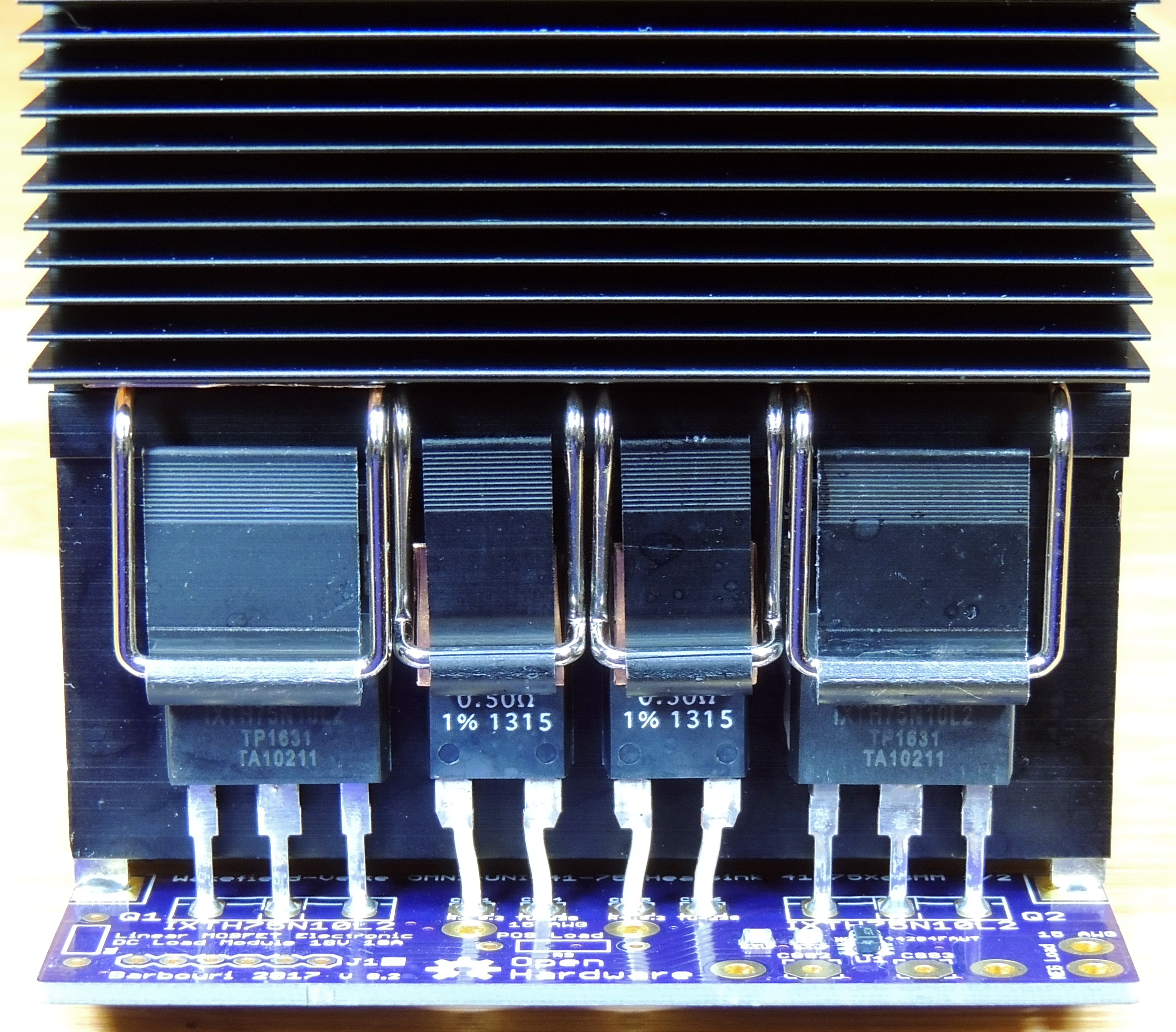
I designed a new Linear MOSFET board for the DC Load project. Now version 0.2 with dual MOSFETS and dual 0.5 ohm power resistors. The original single MOSFET version did meet all the requirements, but at higher loads I was not able to transfer enough heat thru the single package to the heatsink without exceeding my setpoint for junction temperature. I also compromised on the maximum load specifications for the continuous duty current and voltage. Also by changing the max load specification to 18 Volts at 10 Amps, I was able to increase the current sense resistor from 0.005 to 0.01 ohm which will improve the resolution at all current ranges.
Next step in the project is developing a 4 wire PWM fan controller and heatsink temperature monitoring using the Teensy 3.2 board.

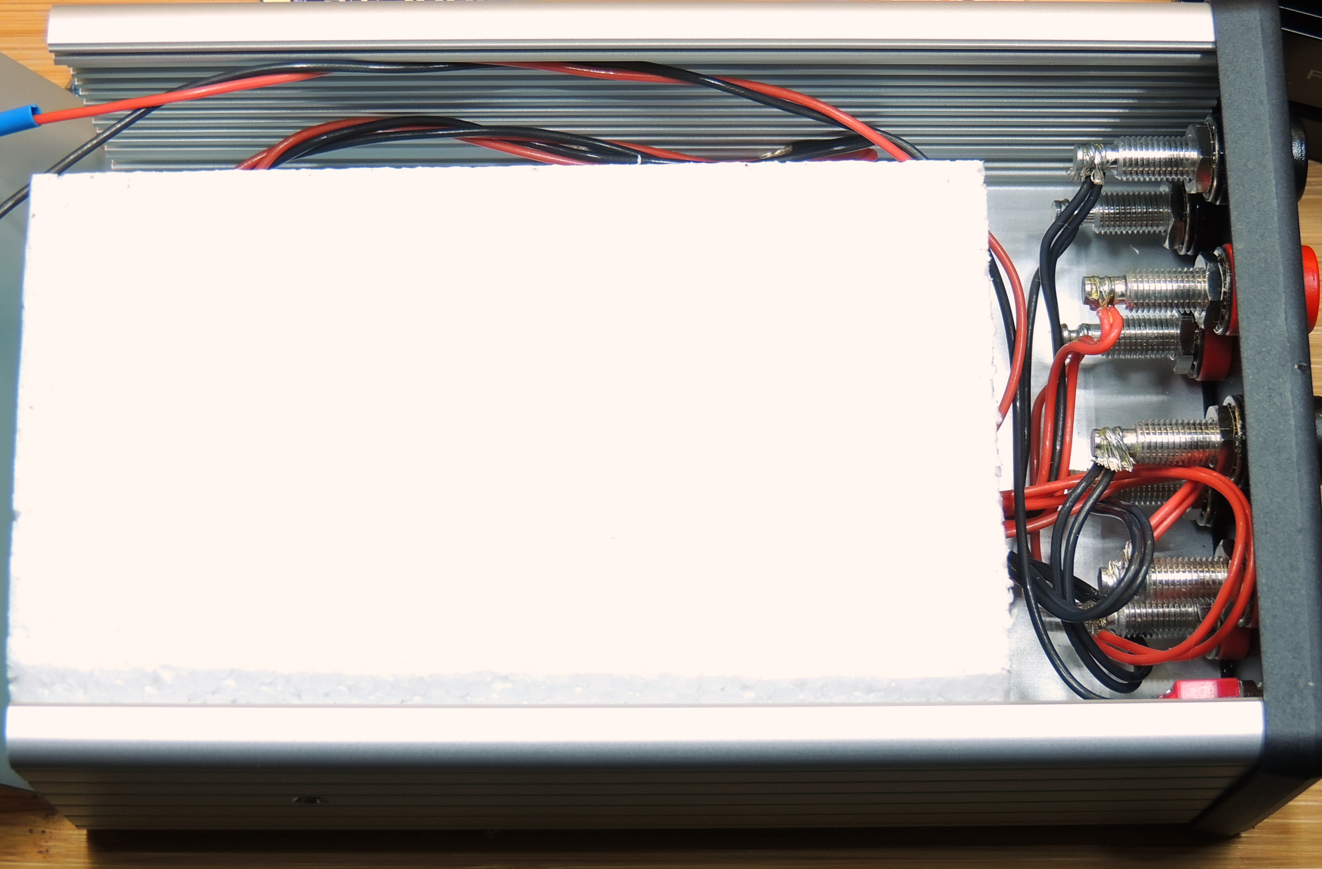
Progress on the Quad Voltage Reference version 2 temperature controlled environment for improved stability. I still need to finish the programing of the ATTiny85 processor and implementing a PID control.

Quad Voltage Reference V 2 insulation for temperature controlled environment.
New series of projects for SDR (Software Defined Radio) reception of ADS‑B aircraft, and AIS marine ship data reception, along with some test boards for mounting voltage reference IC’s.


I can’t help but notice that the current sense resistors pictured in the DC load project are 0.5 ohm, but you mention that the change was from .005 ohm to .01 ohm. Can you elaborate? Also, can you advise the item numbers for the clips that attach the TO-XXX package devices to the heat sink? Many thanks!
Hi Sonny,
The two 0.5 ohm heatsink mounted resistors are not the sense resistor, the 0.01 ohm 4 wire sense resistor mounts just below U1 on the circuit board. The 0.5 ohm resistors are for additional load dissipation and to assist in balancing the current across both L2 MOSFETS. The clips are Wakefield-Vette OMNI-UC for the TO-247 MOSFETS, and OMNI-220C for the TO-220 resistors.
Greg
Greg: Thanks so much for the info.! Sorry I am just getting around to seeing your reply. I am going to have to order a couple of your V2 boards. I just saw your 1090 MHz LNA/Filter project and that one looks fun too.
Thanks again!
Sonny