

Construction and circuit information for the DIY Open EVSE V4.23 electric vehicle charging system.

The DIY Open EVSE circuit board Version 4.23 is used for electric vehicle charging using the J1772 standard. It is an Open-source hardware project which uses the GNU General Public License and is based on the original designs by Chris Howell and Lincomatic.
For the history of the DIY Open EVSE Project, and board changes from the original V1. See my previous post - The DIY Open EVSE Project

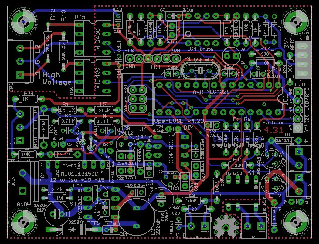
The DIY Open EVSE version 4.23 is my latest thru-hole board version of the Open EVSE charging system. It incorporates the current safety features of the surface mount component versions of the board. It is powered by a 12 volt 5 watt DC power supply, and generates and regulates +5, +/-15, and +/-12 volts DC on the board. The microprocessor IC1, is an 8‑bit ATMEGA 328‑P.

There are 6 main sections of the circuit:
- Power
- Microprocessor
- Pilot
- Safety checks
- Relay control
- Auxiliary circuits
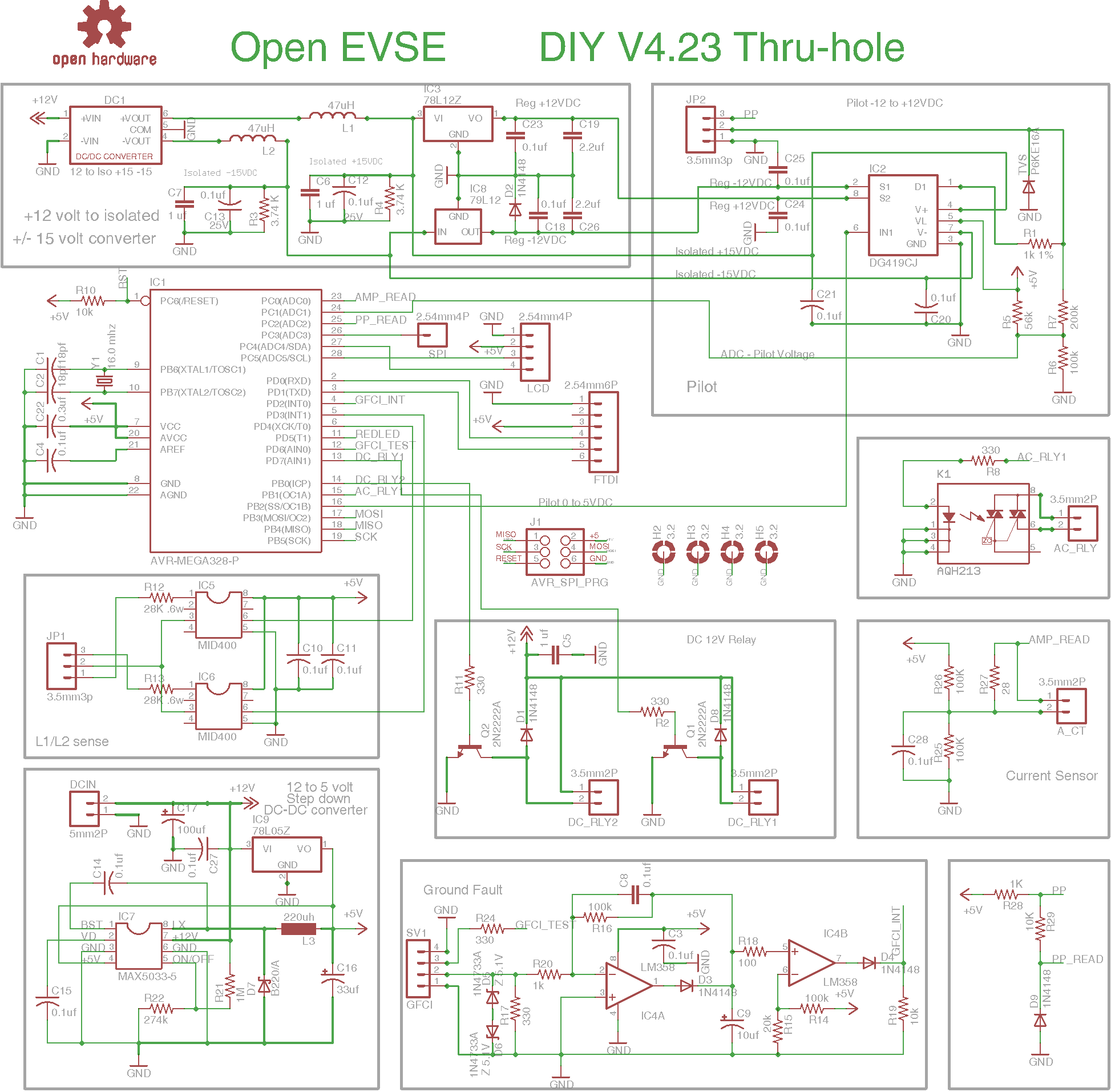
The Power section consists of a 5 volt buck switching regulator, with a linear regulator option footprint, an isolated +15/-15 volt DC-DC converter, and +12/-12 volt linear regulator for the Pilot supply.

The 5 volt buck switching regulator is based on a MAX5033‑5 high-efficiency, step-down DC-DC converter. This pulse-width modulated (PWM) converter operates at a fixed 125 kHz switching frequency at heavy loads, and automatically switches to pulseskipping mode to provide low quiescent current and high efficiency at light loads, and delivers up to 500mA output current.
A cost-saving option for the 5 volt section is to replace the MAX5033‑5 with a 78L05Z linear regulator (IC9 optional) and only populate (C27 optional), C16, and C17 in this section. If the MAX5033‑5 is used, do not populate IC9 or C27.

The isolated +15/-15 DC-DC converter is a Murata 1 watt MEV1D1215SC in a SIP 7 package with 3kVDC galvanic isolation. This supplies power for the DG419CJ switch IC2 and the +12/-12 volt linear regulators IC3/IC8. The outputs of the +15/-15 isolated supply are filtered using the manufacturer recommended LC filter of 47 uH (L1, L2) and 1 uF (C6, C7) and also include a minimum load resistor of 3.74K ohms (R3, R4).
The +12/-12 regulators IC3/IC8 supply stable power to the Pilot switch IC2 and are 78L12Z positive and 79L12 negative linear regulators, both in a TO92 package.

The microprocessor is a Microchip (Atmel) 8‑bit AVR RISC-based microcontroller with 32KB ISP flash memory, 1024B EEPROM, and 2KB SRAM. It features 23 general purpose I/O lines, internal and external interrupts, serial programmable USART, a byte-oriented 2‑wire serial interface, SPI serial port, and a 6‑channel 10-bit A/D converter. The board uses the 28 pin DIP package of the IC. All pins on the IC are used with the exception of ADC3 which is connected to the optional SPI interface header pin SPI.
Analog circuit voltages for AMP_READ, PP_READ, and PilotVoltage are read by the 10-bit ADC on ADC0 thru 2. The GFC (Ground Fault Circuit) is sensed on INT0, and GFCI_TEST on AIN1 supplies current for the GFC test circuit. DC and AC relays are controlled by outputs AIN1, ICP, and OC1A. The 4 pin display header labeled LCD using an I2C interface has Ground, 5VDC, and microprocessor SCL, SDA connections. Output OC1B supplies the 1,000 Hz PWM signal to IC2 pin 6 for Pilot signal control.
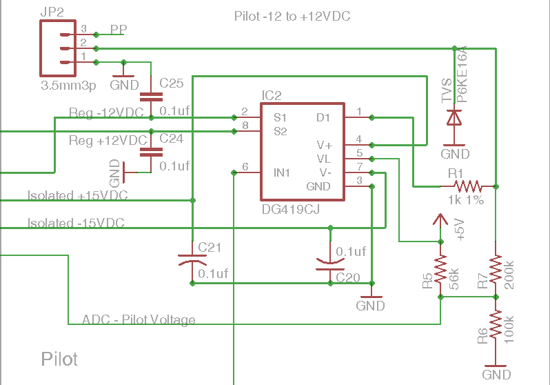
The Pilot circuit is used to coordinate charging level between the car and the charger as well as other information. The pilot signal generated by the EVSE is a 1 kHz square wave at ±12 volts and is used to detect the presence of the vehicle, communicate the maximum allowable charging current, and control charging.
The Pilot circuit is comprised of a Maxim DG419CJ+ (IC2), TVS protection device, limiting resistor R1 1K ohm 1%, voltage divider and biasing resistors R5, R6, R7, and decoupling capacitors. The DG419CJ+ is a monolithic analog single pole/double-throw (SPDT) switch with one normally closed switch and one normally open switch. Switching times are less than 175ns max for tON and less than 145ns max for tOFF. The divider and bias resistor circuit scales the Pilot signal to 0–5 volts and is read by the microprocessor ADC1 input.

Safety Checks:
The GFC (Ground Fault Circuit) is comprised of a LM358 op-amp IC4, an external current sense coil, burden resistor R17, and additional resistors capacitors, and diodes to make a peak detector and comparator circuit. The output GFCI_INT is connected to microprocessor pin INT0 and goes high when a Ground Fault is detected. Resistor R24 connects to pin 3 of the GFCI connector and limits the current supplied by microprocessor pin AIN0(PD6), it is used for testing the Ground Fault circuit. GFCI connector pin 3 connects externally with a multi-turn (5 turns) coil wrapped around the current sense coil that returns to ground.

The L1/L2 sense circuit is used to determine the presence of AC voltages on the relay output terminals. It is comprised of two (IC5, IC6) MID400 optically isolated AC line-to-logic interface devices for monitoring ON or OFF status of an AC input. Resistors R12, R13 are for input current limiting and keep the MID400 in saturated mode when voltage is present. The firmware in the microprocessor performs a safety check on startup by closing the relay/relays and determines whether 120 or 240 volt power is being supplied to the EVSE using the L1/L2 sense circuit, and then opens the relay for a stuck relay check and verifies no voltage present.


The Relay Output circuits include 2 transistor driven DC 12 volt outputs and 1 solid state relay driven AC output circuit. DC_RLY1 is controlled by microprocessor output AIN1(PD7), and DC_RLY2 by output ICP(PB0). The microprocessor outputs, each drive a 2N2222A transistor thru a 330 ohm current limiting resistor. Both DC circuits include a 1N4148 diode for reverse EMF protection from the relay coil and typically are capable of 500 mA loads.
The AC output is controlled by microprocessor pin OC1A(PB1) thru 330 ohm resistor R8. Depending on the SSR part number installed, the 8 pin dip version will typically support up to 600 VAC and 0.6 to 1.2 amp loads. It is recommended to install a surge absorption circuit (Snubber circuit) at the AC relay coil, based on the manufactures recommendation.


Auxiliary circuits include a current sensor circuit and Proximity pilot (PP) circuit.
The current sensor uses an external current transformer (CR8450-1K-T7QC) rated at 100 amps. Resistor R27 is the burden resistor that converts the current from the CT to a voltage supplied to the microprocessor analog input ADC0(PC0). Resistors R25, R26 and capacitor C28 form a voltage divider to provide 2.5 volts DC to bias the positive and negative AC signal from the CT, to a positive range that the ADC can measure.
The PP_READ circuit is for detecting proximity pilot (plug present), and connects to the microprocessor pin ADC2(PC2).

Sample DIY Open EVSE 4.2X Single Relay connection diagramBOM for version 4.2 several small changes between 4.2 and 4.23 include the AC relay, current input, PP_READ, L1/L2 sense, 2nd DC relay output, and GFCI test.
Eagle CAD files for DIY Open EVSE 4.23
OSH-Park DIY Open EVSE 4.23 Project page.
Hi,
I’m about to start build your 4.23 board.
can you please giv some pros and cons of your version vs the openEvse one
Thank You
Hi,
The commercial version basically requires no soldering, while the DIY OpenEVSE requires lots of thru hole soldering.
Commercial version is mostly comprised of SMD parts, while the DIY OpenEVSE uses all thru-hole soldered parts.
Greg (Barbouri)
Hi Greg, great project — did you consider similar thing but with 1206 size SMD components? Would be still easy to solder — the board would be little smaller I suppose. Do you know KiCad? I might make such PCB one day but would need some guidance by more advanced PCB designer 🙂
Apparently I did not explain myself clearly.
There are differences in circuit design, for example you use a 12 volt supplier and apply two conversion options to 5 volts.
There are also differences in the pilot circuit.
Can you please explain the reason for the difference from the commercial version?
Hi,
I’m planning on getting my first electric car next year.
I’m searching for a portable EVSE at reasonable cost, mostly to charge the car away from home, from industrial or caravan sockets, if a charging station is far. The commercial ones are shamelessly expensive. I used to tinker with electronics and I have friends who are in the business, so I want to try building one.
Could your design be used with a 3‑phase, 240/400V, 32A source (Europe)?
How can I get the MCU firmware?
Very nice PCB, at least in the photos.
Thank you.
Hi Szilárd,
The circuit board would need to be modified to work with 3‑phase power.
One extra input in the voltage monitoring section and upgrade to support 400V.
Firmware is available from: GitHub Open-EVSE
Greg (Barbouri)
My Second 4.23 build so first of all Thank you Greg -)
If my unit is L1 240v with one relay, do i have to implement all relay and AC_Test circuits?
I may use this time AC_Relay, so can i skeep the 12V relay circuit?
Technically 240 VAC is L2. You should only need the relay and test circuits for the mode you are using, as long as the unit cannot accidentally be used in an unsupported mode.
I have always used a DPST relay and all required test circuits to support both modes of operation.
Greg (Barbouri)
where’s the ground layer in the layout? Is this a 4 layer or 2 layer?
It is a 2 layer board of 3.34 x 2.55 inches (84.9 x 64.8 mm).
Ground layer is on both top and bottom layers, except for the high voltage AC section.
Greg (Barbouri)
Apologies if I’ve missed something but is there a way to manually set the charging current?
Maximum charging current is set thru the software using the LCD display and push-button.
Software GitHub/lincomatic/Open EVSE
Menu basics OpenEVSE Support LCD Menu
I recently bought a Rolec branded evse that seems to be powered by a knock off openevse board. Its labelled as Rolec ver 1.2 from 2013 and is built into 2 halves to fit into a DIN style enclosure with 12 connections on each side. But it has many of the same chips as the openevse 4.0 type hardware. I would like to see if the firmware is based on openevse and hopefully upgrade it to include newer features like a display and wifi. I found the github repo but is the official board not open source any more? It seems like development has slowed or stopped. How can i connect up to the serial interface and see if this board is running a version of openevse and which one? I can send pics if that would help.
Hi Robb,
From a quick look at the Rolec board, it doesn’t look like it has the I2C display or serial port broken out on the board.
You could reverse engineer the board and add the connections along with modifying the firmware, but it would most likely be easier to just purchase an “OpenEVSE v4 — Universal EVSE Controller” board to upgrade your existing system.
Another option is to build one of the open source DIY OpenEVSE V4.23 boards.
Greg (Barbouri)
Hi,
Can a Polymer Capacitors (KEMET A758EK336M1EAAE040) replace the Vishay tantalum for c16?
Thank you!
Yoav
Hi Yoav,

Yes, that capacitor should work. Or you could also go with a PLF1A470MDL4 47µF 10V Aluminum Polymer capacitor, that has an even lower ESR of 25 mOhm.
I would recommend after design changes to the power supply, testing the circuit before populating the rest of the board with a simulated load.
Greg (Barbouri)
Hi,
The new evse state is always EV Connected , could it be the do to 4.8 firmware?
It is possible that it could be due to changes in the 4.8 firmware, but then it would loose all backward compatibility with all the existing systems.
I would try an older firmware to see if the problem still exists, and if it does then its most likely a hardware problem.
Greg (Barbouri)
I wanted to update that version 4.8 works fine, the problem was one of the resistors — I used the wrong value …
I think you should add a description for AC relay wiring, I would be happy to send a photo as an example.
Hello!
How do I wire a Type 1 plug with a switch on the latch? I measured the resistance, open latch = 480 ohm, closed latch = 150 ohm. The plug is not yet crimped, I just wanted to make sure before crimping. I was planning crimping one of the wires going from the latch switch to PE pin, and the other wire ging from the switch to PP pin. Do I need to connect the PP pin to the PP slot on the EVSE too? Sorry fom my broken english.
Hello,
After a year of use, R12 is completely burned ):
Any idea what could cause this?
The part i use: https://www.digikey.com/product-detail/en/vishay-bc-components/MRS25000C2802FRP00/PPC28.0KZCT-ND/594989
https://photos.app.goo.gl/xs2HoXWwC1BvQWcu6
Thank You,
Yoav
Hi,
The only thing I can think that would cause that type of failure would be a fault on the primary side of the voltage detector IC‑5.
I noticed that you are only using one voltage detector IC. I am assuming that you are using it in L1 charging mode at 120 VAC?
The resistor is rated at 350 volts and 0.6 watts, so it should withstand continuous use at 120 volts.
Greg (Barbouri)
It is single phase 220 VAC, Tha unit manually set to L2.
Hi Yoav,
That’s why the resistor failed. I am surprised it lasted a year.
The sense circuit is designed for a split-phase 240 VAC supply which supplies 120 VAC from each phase to ground and 240 VAC across phases.
Each voltage sense IC (MID400) only sees a potential of 120 VAC to ground. With 220 VAC across a single IC the resistor was dissipating 1.7 watts.
A good starting point for a replacement resistor would be a ROX1SJ56K 56K ohm 1 watt mounted above the circuit board for additional airflow.
Greg (Barbouri)
Thanks Greg,
I think to take the opportunity and add 1N4004 rectifier diode to the circuit.
Maybe soldering the side of the cathode to one side of the resistor and then to the board.
Greg -
I noticed in your diy openevse v4.2 schematic that the display / rtc board breaks out 4 pushbuttons (one select, three options) — but these do not appear in v4.23 schematics.
Is there any support in the openevse v4 (or v5) firmware for discrete pushbutton inputs to enable/disable the charger and select current levels, so that I could use external relay contact closures to control the charger?
Thx -
Hi Steve,
The pushbuttons are part of the OpenEVSE Display V 4.2 board and are included in its schematics.
The firmware as far as I know only supports the select button. I have broken out the additional I/O pins for those who are interested in modifying the existing firmware.
The optional pins can be either programmed as inputs or outputs, depending on the need.
https://oshpark.com/shared_projects/J6RW88kf
Display42 EagleCAD files
Greg (Barbouri)
Hello,
I want to make some space for AC / DC converter (RECOM RAC04-12SGB) on the PCB.
Since I use only AC_RLY DC_RLY circuits will not be populated.
Another idea I have is to switch to ATMEGA328P-AU-ND. The problem is that I do not have enough experience and I’m not sure which AVR crystal and SMD capacitors are appropriate.
If all goes well in the next version I will try and switch to MEA1D0515SC for the +/- 15V and 5V power supply
Thanks
Yoav
Hi,
Where can I find the commercial version ? Is it Open to change ?
Best regards,
Marco
Hi Marco,
Here is a link to the Open EVSE commercial website.
https://www.openevse.com
Greg (Barbouri)
So if I wanted to use different CT coil can I calibrate it by changing just R27 value? I got some inexpensive 100A/20mA coils from China as exact same ones used here are hardly available in my area.
Hi Emce,
Here is a link to a great page explaining how to calculate the Burden voltage resistor R27.
OpenEnergyMonitor CT’s
Greg (Barbouri)
I live in Europe and we have 240V everywhere so L1/L2 charging to be honest doesn’t exist and auto-detection is waste of resources — can I get rid of MID400 completely (so far I see it would be only needed for ground self test — maybe just 1 of them is enough?)
I also don’t use AC coils based relays so I understand that AQH213 and it’s resistor are not needed for board to run just fine?
Hi Emce,
The MID400 voltage detectors are part of the safety circuit, and also can be used for L1/L2 detection.
Their main safety purpose is for stuck relay detection. Both sensors are required for normal 240V operation.
The AQH213 is optional and was only added to support the current firmware at the time.
Greg (Barbouri)
Hi Greg,
I’m not 100% sure but I think openevse 5.x works with just one MID400. Do you have any plans for THT version of OpenEvse 5.x?
Regards
Hi Emce,
If you do decide to go with the single MID400 circuit, see the comments from “Yoav Levy” above and how to implement.
I do not currently have any plans for future versions of the DIY OpenEVSE board.
Greg (Barbouri)
Can I replace R3 and R4 with something else? BOM file says they’re 2.8k — eagle file 3.74k — both hard to get here as THT.
Hi Emce,
You should be able to use 3.6K ohm resistors which are E24 Standard Resistor Series 5% type.
If those are not available you could try a 3.3K ohm 10% E12 series.
These are the minimum load resistors for the Murata 1 watt MEV1D1215SC isolated power supply.
Greg (Barbouri)
Is something wrong with my board because I’m always getting diode check error? Even when connected to the car or EVSE simulator.
Hi Emce,
The first thing I would check is the ground connections inside the EVSE unit.
Does it start charging with the “Diode Check” setting disabled?
Greg (Barbouri)
Hi Greg,
Yes it works just fine with this test disabled.
So it charged with diode check setting disabled but recently I got Tesla to charge and it didn’t. So I removed board from my charger and here’s what I see. R1 i 999Ohm (1%) . With 12V connected on DG419 I see: PIN1 12V, PIN2 ‑12.2 PIN3 0, PIN4 15.2V PIN5 5V, PIN6 5V, PIN7 ‑15.2V, PIN8 12.1V. When I connect car on PIN1 I see 0.7V but I would expect to see some negative values (my original openevse shows ‑2V). During this time I see 0.26V on PIN6 and 1kHz signal so PWM works as expected. I have also checked pilot monitor resistors and R7 is 199k, R6 99.4k, R5 55.2k — any idea what to check next?
Ok issue found — it’s P6KE diode — mine was not bidirectional
Also I did connect everything as on your previous post picture (about history of evse versions). Ground seems to be ok as ground test doesn’t complain at all and it was when ground was not connected.
Hi Barbouri. I can’t understand how do you measure Input AC voltage? As I understand your software calculates Watts and Wh. I can see the current transformer, but anything for the voltage. As I understand from the MID400 documentation, it can only detect AC presence, but not amplitude.
Hi Roman,
The system guesses at the voltage depending on whether it is charging on L1 or L2 and uses a voltage constant set in firmware.
It would be possible to recompile the firmware for a different voltage constant.
There have been several users of the commercial version of the openevse who have modified their systems to read AC voltage.
Here is a link to one of the better documented modifications to a commercial V4 board:
V4 voltage input modification
A3 is brought out to a pin next to the display connector on the DIY 4.23 and later boards.
Greg (Barbouri)
Thank you, Greg!
Hello,
Very nice work, but I’ve got a question.
You are reading the “Pilot Voltage” with an ADC input, but it is fluctuating all the time (just if the EV is connected) because you’ve got the PWM signal. So, how can you discriminate the status of the car?
Thank you!
I’m finding problems on getting P6KE16A — can I replace it with something else?
Hi Marcin,
The P6KE16CA is a 13.6 volt 600 watt bidirectional TVS Diode.
It can be replaced with any equivalent or higher wattage rated TVS diode such as the 1.5KE16A-E3.
The P6KE16CA is currently in stock at https://pl.mouser.com/
Greg (Barbouri)
Hi Greg,
This is a very nicely explained project.
I wanted to know whether you’ve experienced a slow processing time with the atmega328 controller?
For me the relay actuation, LCD state changes etc are taking more time than usual (approx 5s) after the code execution.
I’ve uploaded the default firmware from https://github.com/OpenEVSE/open_evse/releases
Thanks and Regards
Vasu
Hi Vasu,
Relay and display state changes happen almost instantly with the ATmega328P.
I have tested using version 4.6.0 of the firmware, but haven’t tested using the newer versions.
Greg (Barbouri)
Thanks Greg for a prompt reply!
I just tried with the older version — 4.6.0 and the problem still exists.
I’m using the USBasp to flash, can this also be a hardware issue?
Is there a troubleshooting method I should follow ?
Hi Vasu,
Very well could be a hardware issue.
Since everything is working, but slow, a clock / frequency issue. Try a new ATmega328P.
Possible improper fuse settings for the ATmega328P.
lfuse:0xFF hfuse:0xDF efuse:0x05
Greg (Barbouri)
Thanks Greg, that worked.
Default fuse settings were the culprit
Hi Greg,
I’ve used your PCB design for level2 charger and I’ve tested the PCB for general safety checks and control loop. So far, everything is working as expected. Now I’m planning to test the charger on an EV with 32A.
Is there something else I should be careful about, any resistor network which is crucial and can burnout?
Hi Vasu,
I usually use some test resistors and diode on the pilot line to make sure it goes into the right modes.
My only other suggestion, would be to start out on a lower setting, such as 12 amps for a few minutes, then disconnect everything and check the temperature on all the high current connections before ramping up the power.
Greg (Barbouri)
Hello Greg,
Today I tested the charger on an electric vehicle. I had set the current at 6A for safe charging.
For initial 2–3 seconds the car status changed to charging, then I got an error on LCD stating ‘service required- overcurrent 102A’ and the relay tripped. I was surprised to see a bizarre current of 102A as the Max load was only 7.5KW at 220–240V.
Any suggestions for troubleshooting this?
Hi Vasu,
Check the minimum charge current for the vehicle you are charging. Some have a 10–16 amp minimum charge level.
Next, I would check the current sensor on the DIY Open EVSE. There should only be one wire passing thru the sensor.
Greg (Barbouri)
Yes there’s only one ‘Main wire’ passing through the CT coil.
The bizarre current sensing could also be because of incorrect resistor values of A_CT on the PCB schematic. In the schematic R27 is 28ohms, in my PCB its probably a 10K ohm resistor value which looks like a fabrication fault.
Could be a logical culprit?
Hi Vasu,
R27 is the current transformer burden load resistor. The DIY Open EVSE is designed to use a current output Current Transformer sensor.
The burden resistor converts the CT into a proportional voltage that the microprocessor ADC can measure.
A 10K resistor in R27 could allow hundreds of volts at the microprocessor ADC pin.
Link to more information on CT’s and burden resistors. Open Energy Monitor CT’s
Greg (Barbouri)
Hi Greg,
Thank you for your reply, the direction surely helped my charger. The issue was in the burden resistor R27 have used a 30ohm resistor
I performed another test for one hour on Mahindra E‑Verito which has a rated charging capacity of 2.2KWh.
The EVSE after one hour showed 3.2KW at 14A even after setting the current at 11A.
Is there a calibration setting which I can further tweak to minimize the difference in output reading?
Have also read some google posts which says burden resistor should be 22ohms, is this logical?
Hi Vasu,
The burden resistor is directly related to the current transformer used and the desired range.
Here is a link to a burden resistor calculator: open-energy-monitor-calculator
System voltage is 5 volts.
Greg (Barbouri)
Hello Greg, hope you’re well!
My design looks complete. Although, I’m struggling a bit with understanding the LCD code in the firmware. Do I strictly need to use Adafruit RGB 16x2 LCD that you’ve mentioned in the BOM. As it was unavailable, I tried using a regular 16X2 LCD with Blue Backlight with the same source-code and it didn’t work for me.
Thanks
Hi Vasu,
The standard firmware is setup to use a 16x2 RGB LCD display with a HD44780 controller. The interface uses I2C communications from the main board and converts the I2C to the LCD HD44780 parallel interface on the display board.
If you are not getting any characters on the display even without the backlight check that the SCL and the SDA signals are not reversed.
Greg (Barbouri)
Hii Greg,
Hope you are doing well. This is an insightful open source PCB design for AC chargers .Have you also applied your own design for a DC charger ? It will be helpful for me if you can share some insight on that.
Hi Akash,
I have only worked with AC chargers.
I know the working theory of DC chargers, but haven’t had the need to build one for myself.
Greg (Barbouri)
Hii Greg,
Hope you are doing well.I was planning to use an AC contactor whose coil voltage is 110 and 230VAC. Which RLY terminal(DCRLY1/2 or ACRLY1) should i use in this existing circuit
Hi Akash,
You should use the AC_RLY terminal for AC coils.
If you are using a 230 VAC coil I would also recommend Panasonic part number AQH3213 for the solid state relay IC.
Also recommended to install a surge absorption circuit (Snubber circuit) at the AC relay coil, based on the relay manufactures recommendation.
Greg (Barbouri)
Hii Greg
Thanks for the prompt reply.
My AC contactor is not working .Now I am planning to use a Fotek SSR( Solid State Relay) 40A Rated. But i have read online that SSR have heating issues at high switching cycle and load for which heat sink is required . In my case , SSR will work at 32A (I‑Max) for around 12 hours a day . Will this be suitable for my case?
Hi Akash,
SSR’s are not recommended for use in an EVSE.
Hi Greg,
I am seeing in you are using an isolated +-15V and then convert it it to +-12V via 78L12 regulators. The mentioned parts are not easy to find in our Contry, thats why I have to find some replacements.
I have found a +-12V ACDC supply: RAC10-12DK/277 (https://docs.rs-online.com/2f24/0900766b8161b79a.pdf)
Is there any drawback to use this one directly for the control signals? Why is this 15V -> 12V conversation needed?
Thank you!
Gergo
Hi Gergo,
The DG419 (IC2) needs a +/- 15 volt supply to support the +/- 12 volt pilot signal.
Instead of having a separate +/- 12 volt supply the pilot supply voltage is regulated down from the existing +/- 15 V supply.
The RAC10-12DK/277 supply will not work in this circuit, without an additional +/- 15 volt supply.
There are several simpler EVSE designs that do not require a +/- 15 volt module.
Greg (Barbouri)
Hi,
I’m planning to build this PTH version of the OpenEVSE, the commercial version is still out of stock.
Have a question about the FW: what is the latest official FW which is compatible with this HW version? My plan is to hook it up to an ESP WiFi module and integrate it into smarthome (Home Assistant).
Any advice is welcome.
Hi George,
I have tested my Version 4.2 DIY Open EVSE hardware board with firmware version 4.6.0, along with Open EVSE Wi-Fi version 2.9.0 running on a ESP8266.
I haven’t checked out the newer versions, as the firmware currently in use works great.
Greg (Barbouri)
Hi Greg,
Thank you for the quick reply. Now it is quite straightforward to build and set up this charger.
Before I go any further, I’ve checked the availability of the components. I can’t seem to find the Murata MEV1D1215SC DC-to-DC converter at any supplier. Is there any substitution for this which is available?
George
It looks like the MEAN WELL MDD01M-15 Isolated Module DC DC Converter 2 Output 15V ‑15V — 34mA, 34mA 10.8V — 13.2V Input Digikey #1866–3372-ND
would work as a replacement. It is in stock currently at Digikey.
There is currently a shortage issue with many DC-DC converters as you might have noticed.
If you are unable to get parts, I do have several prototype version 4.2 assembled boards sitting around.
Greg (Barbouri)
Hi greg , I hope my comment find you well. I’m trying to build an evse like yours but with some adjustments. the project will be very simillar with following modification: Board should be powered by two different voltages (mono phase and three phase). The case of the charger will have two inlet ports (C21 for 240v — it is supporting 16A but i will draw max. 10A) and (industrial one 60A with 5 pins, car will use 32A). I will also use an four pole contactor with a 240v coil . This is in theory on the paper, but i need your advice. 1 What do you think about my ideea ? 2. How do you think i should manage voltage reading, safety test, intensity and power consumtion from hardware point of view ? Thank you in advance .
Hi Alex,
Unfortunately the existing board is only designed to accommodate single or split-phase power inputs. The board will need to be modified for monitoring three separate power legs for safety.
The existing board only has two voltage monitoring inputs. So for three phase another monitor circuit will need to be added, or an external monitor module tied to one of the spare inputs.
Greg (Barbouri)
Hi,
do you have a version to control an EV charger 3PN 400V 22 kW 32A per phase?
It is currently only setup for two phase.
The board files are available and can be modified for supporting “3PN 400V 22 kW 32A” along with what should be some minor software modifications.
Greg (Barbouri)
Hi, nice project, very well detailed altough i am wondering how do you calculate the actual kw since there is no voltage reading of L1/L2 for the “real” math? or you assume it is fixed 220v ?
Thanks for any detsails about this
regards
Pat
Hi Pat,
You are correct, the DIY Open EVSE has no built in hardware provisions for measuring mains voltage.
Here is an excerpt from the commercial Open EVSE support page:
“OpenEVSE hardware does not currently measure voltage. The voltage used in energy calculations is assumed to be 120v for L1 and 240 for L2. This value can be changed with a RAPI command or updated real-time with a external source via MQTT.
https://openev.freshdesk.com/support/solutions/articles/6000249626-voltage-displays-240-how-do-i-set-to-something-different-
I believe that it can also be hard coded in firmware to a specific voltage.
Greg (Barbouri)
thanks for the reply
do you believe that available market chargers (Wallbox, Evduty, FLO, Tesla,…) do this as well ?
doesnt seem to be very popular to do that altough most claim 1% power readout accuracy,
thanks.