

Cleanup, repair and Calibration of a Power Designs Inc. C500 Precision DC Source.
Another lucky Ebay score of a used Power Designs Inc. C500 power supply. The supply was described as “Powered Up Only, Untested”, with very poor blurry pictures. It seems that whenever I see blurry pictures on Ebay the seller doesn’t want you to know how bad of shape the item is in, so it was definitely a gamble bidding on this unit.
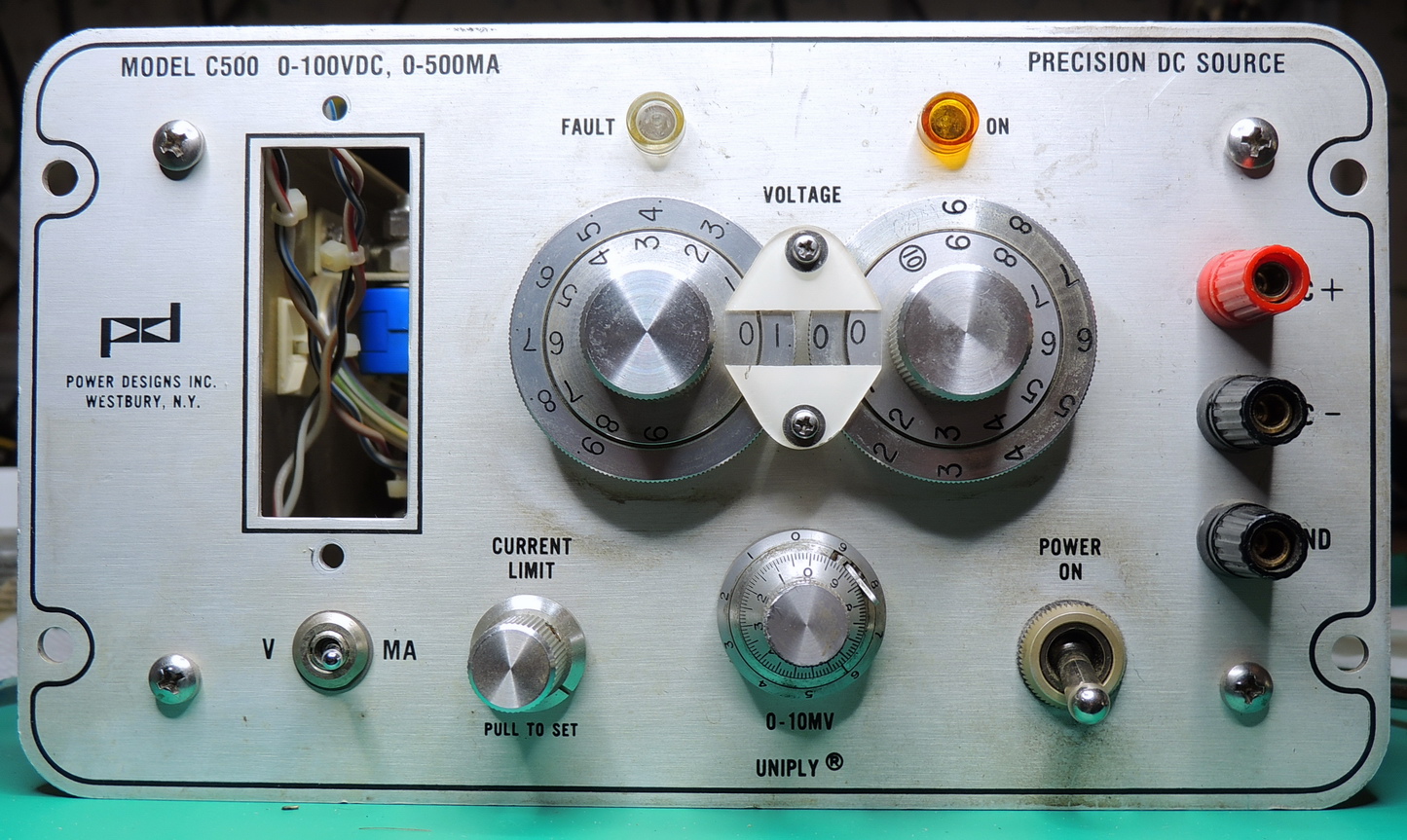
The power supply did arrive mostly well packed, and as expected was very dirty when unwrapped. The biggest problem was the acrylic meter face had been damaged by some type of solvent making reading the meter next to impossible. One of the back feet was missing, and I could hear what I hoped was its attachment screw rattling around inside.
Specifications:
Output voltage 0 — 100 VDC, current 0 — 0.5 Amps
Regulation 0.001%
Ripple and Noise 100 uV P‑P
Stability per 8 Hrs. 0.001% +100 uV
TC per degree C 0.001%
Source Impedance Less than 0.002 Ohms at DC
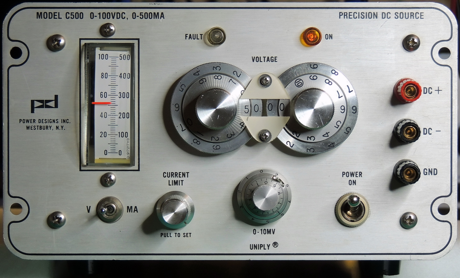
First order of business was to see if the panel meter was repairable.

The meter body and movement were in good shape along with the rest of the front panel. I was able to remove the acrylic lens from the body to work on it which made the repair much easier.
I started the acrylic repair by wet sanding with 1000 grit sandpaper on a precision flat. I then moved to 1500 grit wet and then finished the polishing with Novus plastic polish #2 and then #1.
This C‑500 power supply was built in the later part of 1985 and had 32 years of accumulated grime built up on the front panel and a similar amount of dust inside the cover.
The decade voltage selector switches were very dirty also and during testing had variable contact resistance. A good cleaning with DeoxIT-D5 and then DeoxIT Gold fixed that problem.

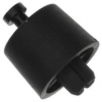
I replaced the missing and existing back feet with a close match from Digikey Part# RPC1130-ND. Made by Essentra Components SFF-028, Santoprene Black. I did end up cutting off the the expand attachment on the foot and used 4–40 screws.
After cleaning, and some basic resistance and capacitor checks it was time to power up the unit.
The PD-C500 powered up with no issues, and after a 30 minute warmup I decided to check the calibration.


Voltage calibration is fairly easy, and requires a 5 1/2 digit voltmeter with better than 0.1% accuracy.
(Warning, calibration requires operation with the cover off and high voltages present internally and on the output terminals.)
Start by un-tightening the locking nuts on R42 and R43 potentiometers.
To calibrate set the decade switches to 0 volt output and rotate the front panel vernier control fully counterclockwise. Set the “Zero” volts adjust (R42) so that the voltmeter reads 0 volts +/- 50 microvolts.
Tighten the locking nut on R42 and re-check the zero reading.
After performing the Zero calibration perform the maximum voltage adjustment. Set the decade switches to the maximum output voltage, which is 100 volts DC on the C‑500, and rotate the front panel vernier control fully counterclockwise. Make sure the least significant digit is set to “10”, not “9”. Adjust the “CAL” potentiometer (R43) for a voltmeter reading of 100.000 volts DC +/- 0.001 volts.
Tighten the locking nut on R43 and re-check the 100.000 volt reading.
Zero calibration on my PD-C500 was only slightly off (-250 uV), and at 100V it only required 1.5 mV of adjustment. Noise and ripple at 50% load was around 12 uVAC.
Once again just shows that Power Designs Inc. made some very fine equipment 30+ years ago and is still usable today with just a little care and maintenance.
