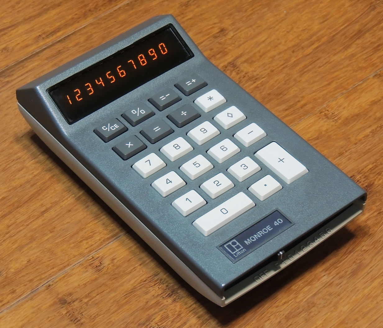
An early handheld calculator from 1974, with a 10 digit Panaplex display and rechargeable battery.
As I continue searching for Monroe 400 series calculators, I came across this Monroe model 40 calculator at a reasonable price, with a few small issues.
Normally I don’t have an interest in handheld calculators as most are too new. This one caught my eye with it’s unique styling and 10 digit Neon Panaplex II display.
The previous owner stated that the calculator worked fine when plugged-in, but the battery pack would not hold a charge. Other than some scuffs, a lightly scratched display bezel, and 49 years of accumulated dirt and grime, this calculator was in overall good shape.
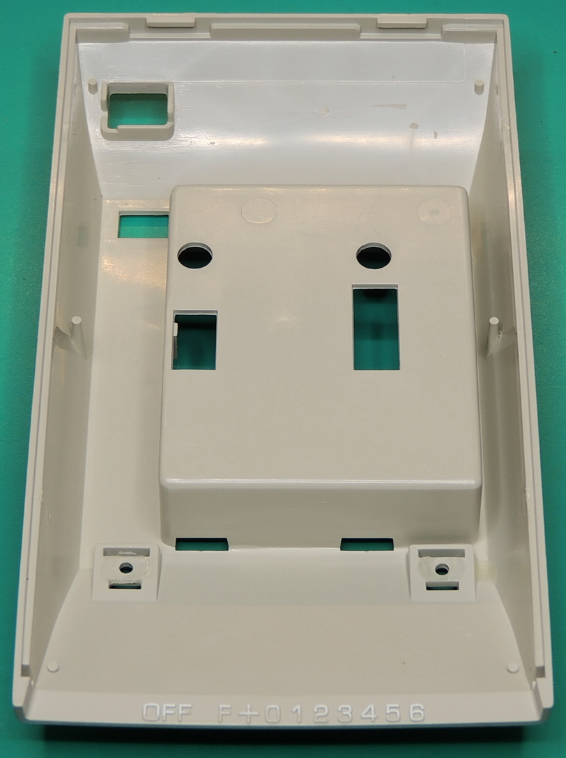
Before turning it on, I removed the lower case to inspect for anything that may have come loose during shipping, and to get started on cleaning the case and battery compartment door.
Upon removing the case and battery I quickly found what was most likely the problem with the battery not holding a charge. The negative contact for the battery on the power board was heavily encrusted with corrosion and preventing a connection with the battery terminal.
After quite a bit of scrubbing with DeoxIT D5, I was still not getting low enough resistance measurements from the contact, so it was time to bring out the 1500 grit wet/dry sandpaper. After several minutes of careful sanding and then a quick follow up of contact cleaner to remove any residue I had a good low resistance contact.
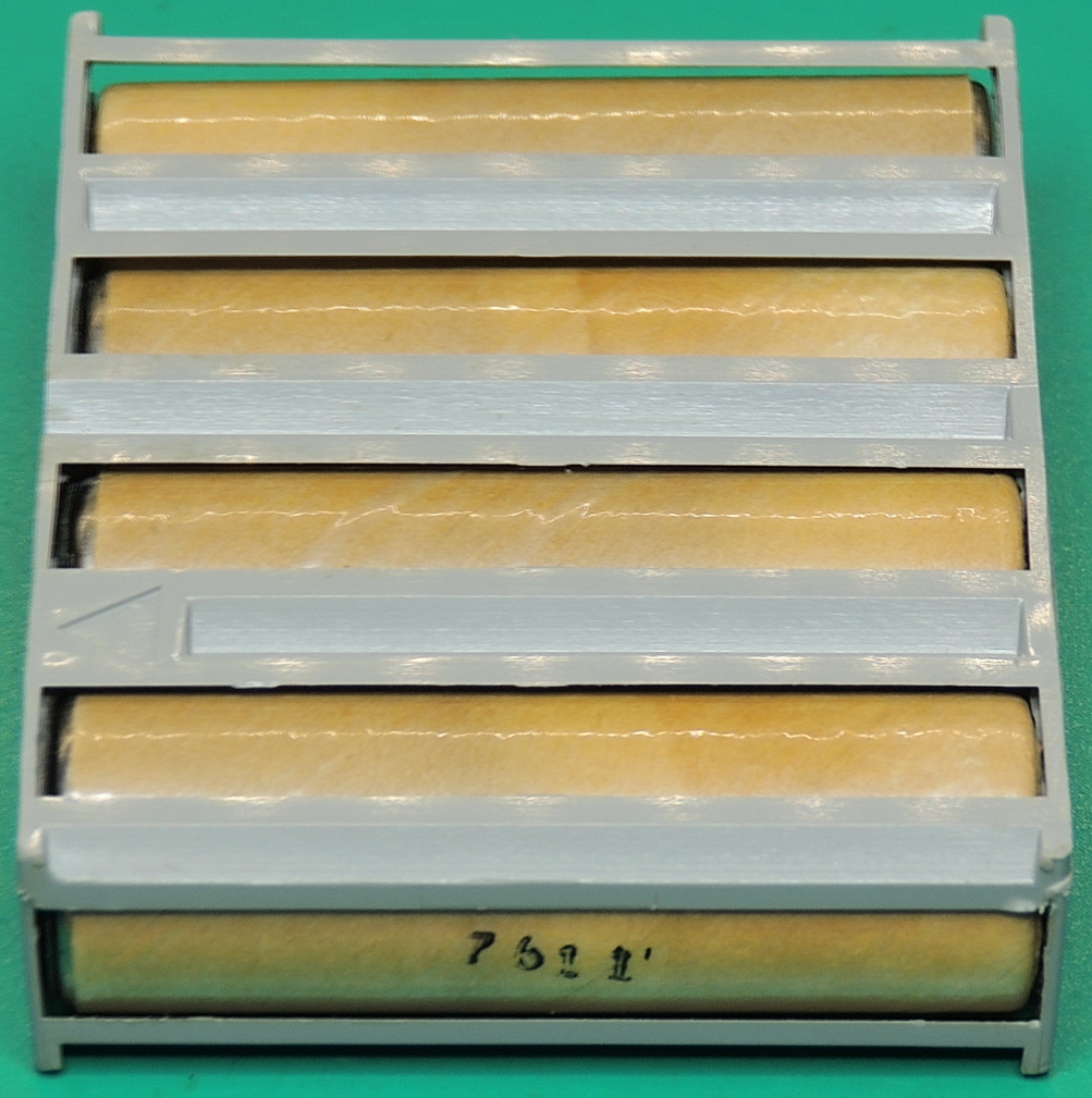
The battery pack is made up of four Ni-Cd batteries in series for a nominal output of 4.8 volts. The pack is held together with a plastic skeleton case with an arrow on top marking orientation, and two contacts on the bottom of the pack.
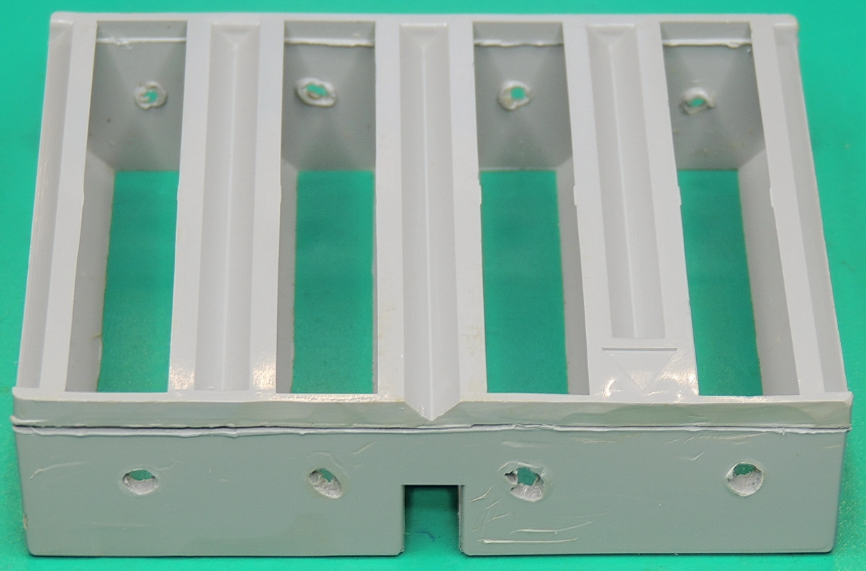
One of the previous owners must have been having issues with the battery as they used a soldering iron to melt holes in the case where the cell contacts would be located. Using the holes in the case I checked the cell voltages and in general all cells were below 1 volt.
I decided to connect the pack up to my Hewlett Packard / Agilent 6632B power supply to see if I could get the pack to accept a charge. My charge settings were 5.8 volts and a current limit of 120 mA.
The pack was accepting a charge, but when checking the individual cell voltages using the holes in the plastic holder I was getting some very odd readings, with some cells showing twice the expected voltage.
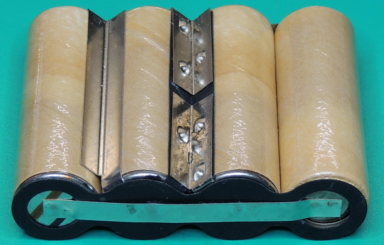
I decided to remove the cells from the holder, by scoring one side of the plastic case at the weld line. After some gently prying I was able to wiggle out the cells by spreading the case apart.
It didn’t take long to realize why I was getting my odd readings from the cells. A quick check of the actual cell terminals showed all the cells were charging at close to the same voltage which was very good.
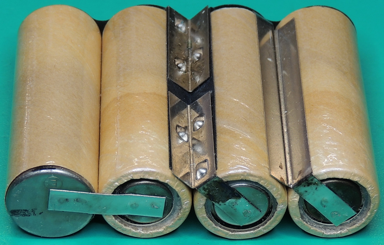
To get the positive and negative terminals in the center of the pack the designers used some creative cell strapping to accomplish it.
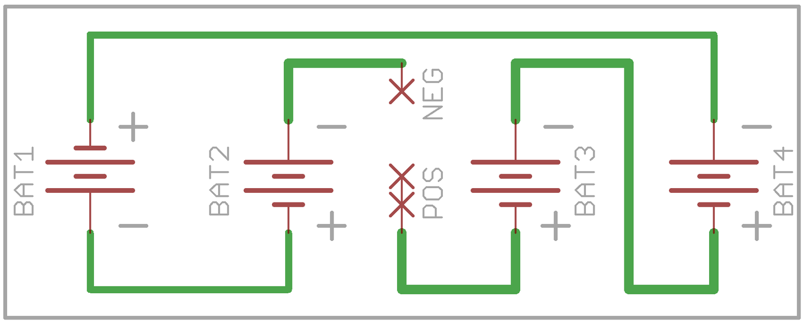
All of the holes on one side of the pack only made contact with the long connecting strip. and two terminals on the other side access the connecting strip of two cells. Using the exposed terminals and four holes it is possible check each individual cell voltage.
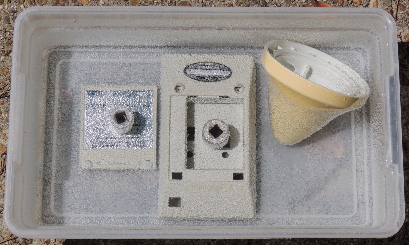
Now that the battery dilemma was solved it was time to continue cleaning the calculator. Most of the case and keypad cleaned up well, but there was still some yellowing of the beige case that needed additional work. I had purchased a gallon of 12% hydrogen peroxide solution quite a while ago and this was my sixth reuse of the solution. It is still working good but I can tell that it is getting towards the end of it’s useful life. The case only needed around 5 hours in mostly sunny conditions to remove all the yellowing.
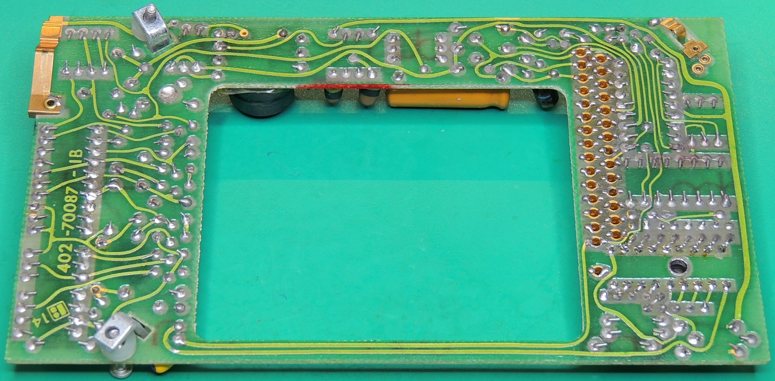
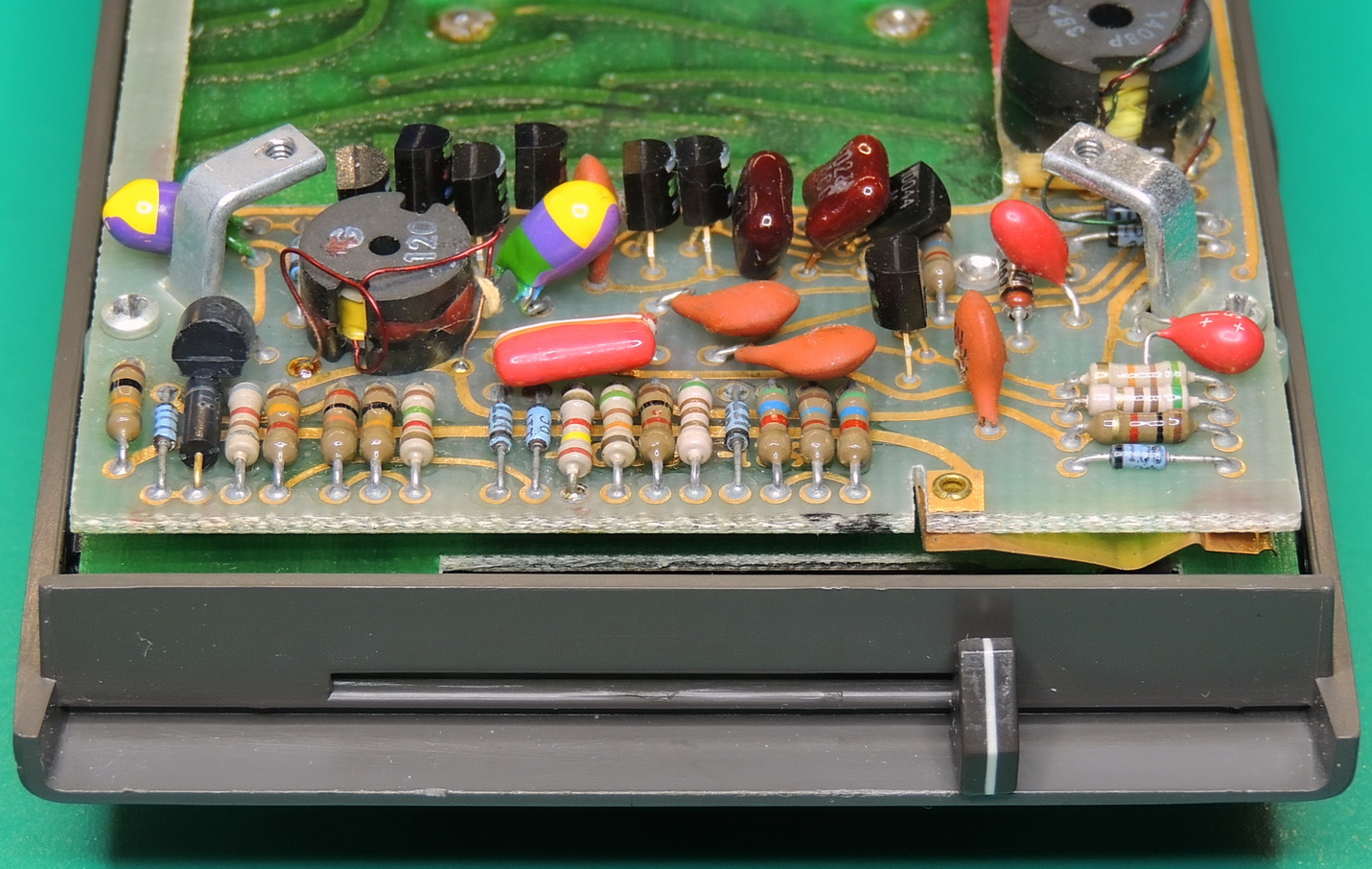
The power / HV board is connected to the main board with two long screws which also support the two case brackets, and a 30 pin inter-board connector. The end of the power / HV board has the power switch which is activated by the sliding power / mode switch lever which is mounted to the upper case.
There are two semi-rigid foam spacers between the two boards, which I assume are meant to keep the connector ends of the boards from contacting. I added some kapton tape to the main board just incase the foam deteriorates in the future. Most likely not necessary but I had it nearby so why not.
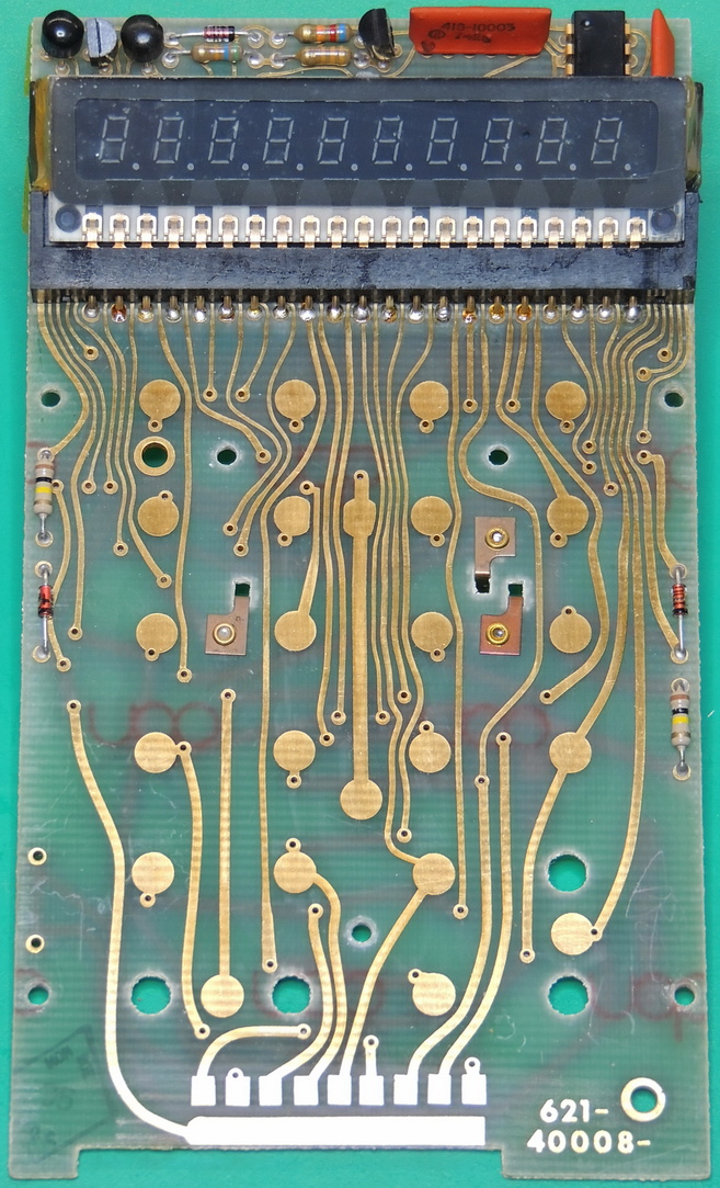
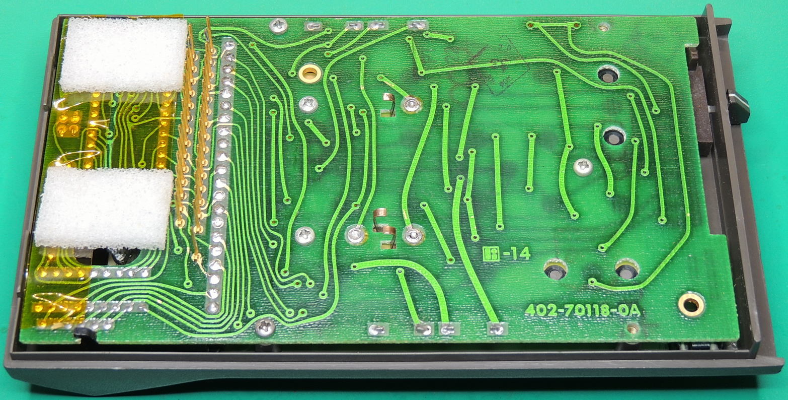
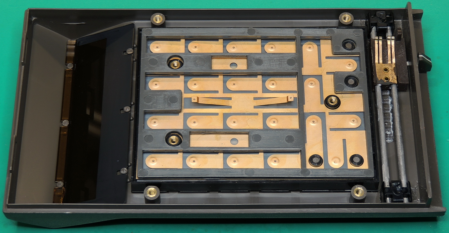
The main board is attached to the top case with 5 screws, with the two outermost screws being longer in length. The mode slider switch pads are visible at the bottom of the board, along with the keypad contacts and center common contacts.
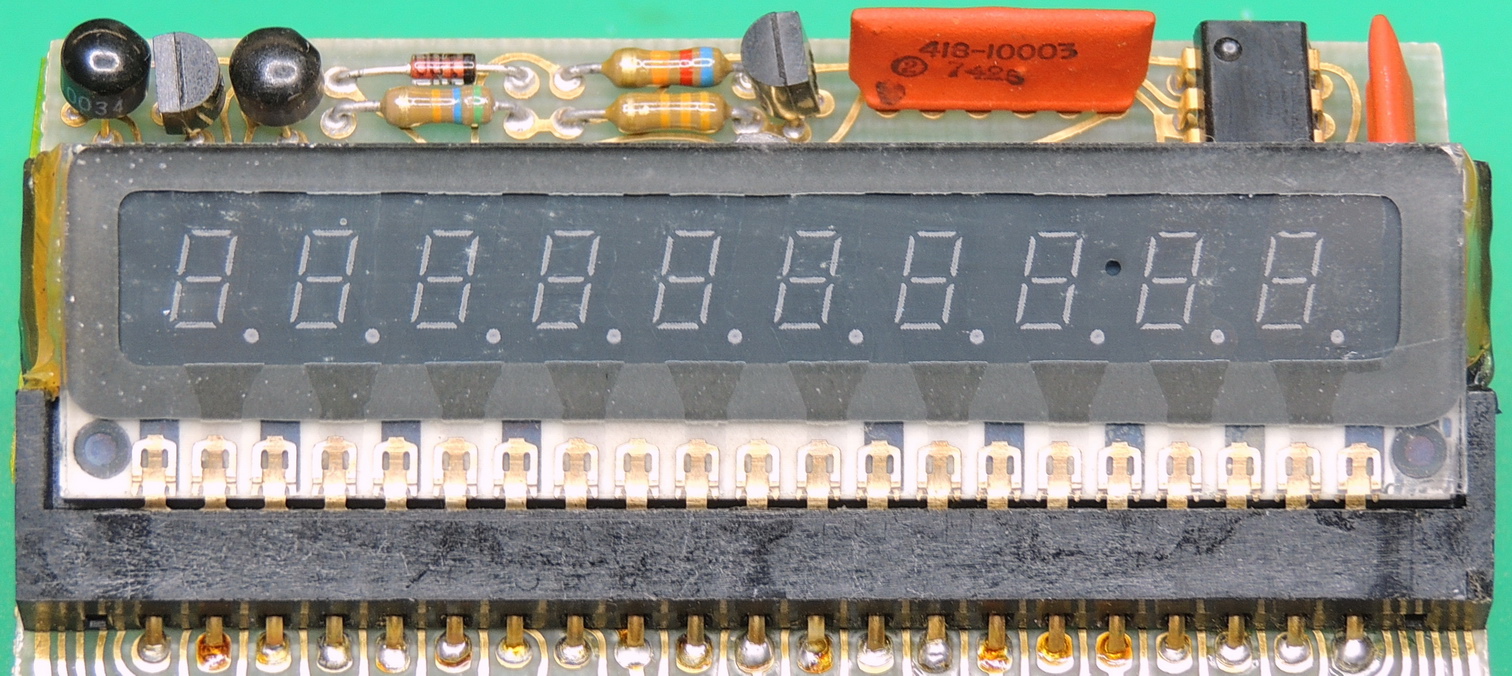
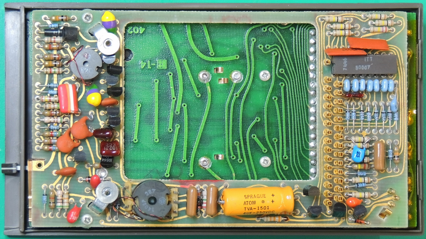
The Burroughs Panaplex II Neon gas-discharge display is attached to a socket and held in place with a hot-melt glue on each side of the socket.
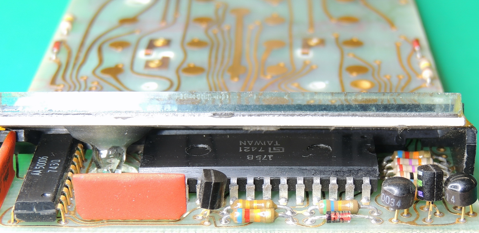
Tucked away under the Panaplex II display is the MOS-LSI General Instrument 175B calculator on a chip IC, along with a display driver and other components. To the left of the 175B is the glass vacuum seal for the display with a cutout hole in the main board to isolate and protect it.
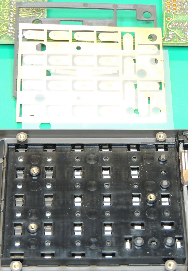
The keypad is made up of several layers stacked on the keypad frame. First a thin translucent plastic sheet, next the metal common contact sheet, and then a grey plastic spacer above the main board contact pads. The keypad sandwich is held together by the three mounting screws.
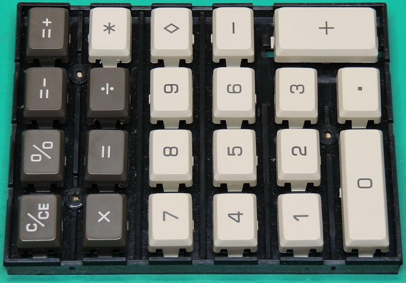
The keypad includes separate Total, Sub-total, +/= and -/= keys. Along with percent and standard ASMD function keys. The zero and + keys are enlarged for ease of use.
The upper case has a tinted bezel that is held in place with heat flattened plastic posts. Brass inserts are used for all screw connections. The power / mode slider is attached to two metal rods attached to the case. I used some Novus #2 plastic polish and cotton tipped applicators for buffing out the scratches on the outside of the bezel. This took quite a while, but I was pleased with the final results. To finish it up I applied some Plexus plastic cleaner, protectant, and polish which made the bezel look almost new.
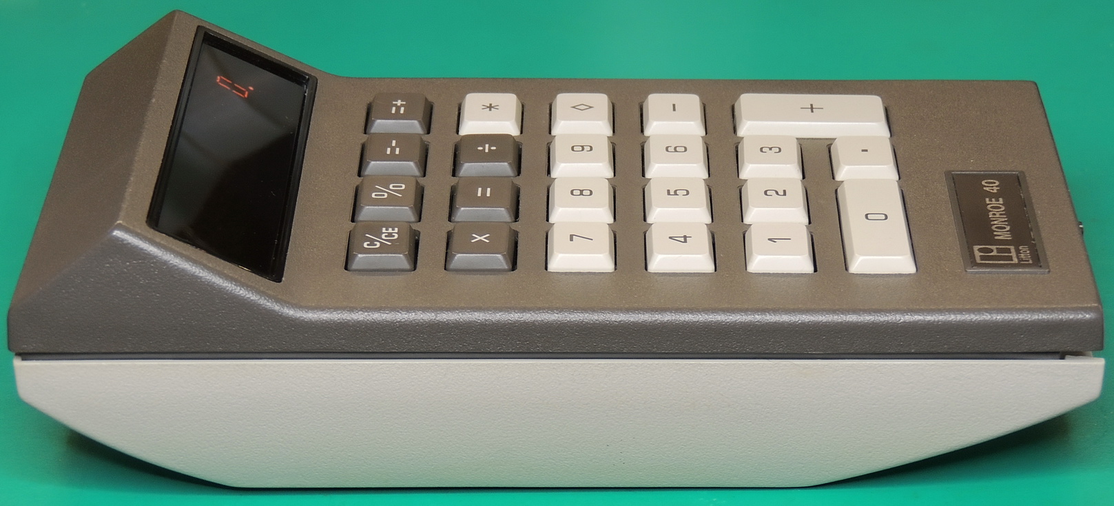
The power / mode slider switch has 10 positions. The modes include Off, full floating point operation, adding machine mode, or a choice of 0 to 6 fixed decimal places.
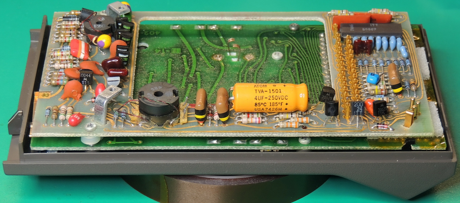
I checked the only electrolytic capacitor with my Peak Atlas ESR70 meter and it was in excellent condition. The capacitor is part of the high voltage supply for the Panaplex II display. The voltage across the capacitor was 202 volts with a single zero on the display after clear. The voltage dropped to 187 volts with 10 eight’s filling the display with very low AC ripple.
The DC power input pins measured 6.5 volts on the pin nearest the connector in-place switch, and 4.3 volts on the pin opposite the switch, with the center pin as common. This doesn’t quite match up with the external power supply specification of 6.8 and 5 volts, but the calculator is working fine at these levels.
Overall I really like the design of the Monroe 40 calculator.
Litton Monroe built a well engineered and compact unit considering the components available at the time of design and construction. The power / mode switch at the front of the calculator is novel and a good use of limited space on this size of calculator.
Though my favorite feature is the beautiful Neon orange glow of the Panaplex display, which is what originally spiked my interest in acquiring this calculator.