

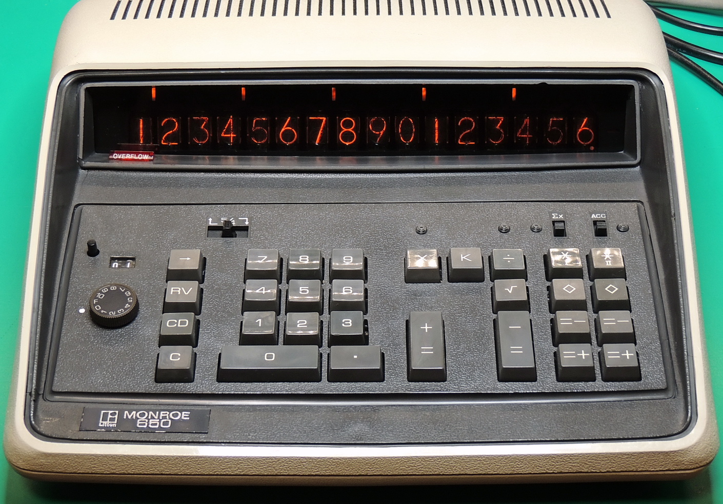
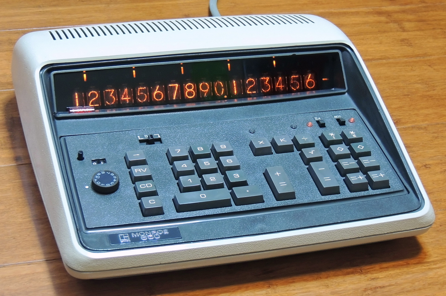
Welp, another calculator tale of woe. This time it is a Monroe 650 calculator found on eBay. The 650 is the top-end model of Monroe’s 600 series calculators. It is a 16 digit Nixie tube display calculator with addition, subtraction, multiplication, division, square root function, and two memories. It operates in fixed decimal or floating point modes, and has 5 changing indicators spaced every increment of the base-10 exponent of three from the decimal point.
The price was right and included free shipping.
What is it with some eBay shippers that think their job is done once the item is sold.
Once again a seller packed a delicate item in a thin 29 lbs./inch rated cardboard box that was too small for the calculator, and then use a single layer of medium-density foam which is much too stiff to provide much of any shock prevention.
This is what happens when that is combined with FedEx Ground shipping.
The other side was not in any better condition. And then to top it off communicating with the seller was frustrating and totally useless.
It’s great that I like fixing things, because I definitely had quite a bit to fix on this project.
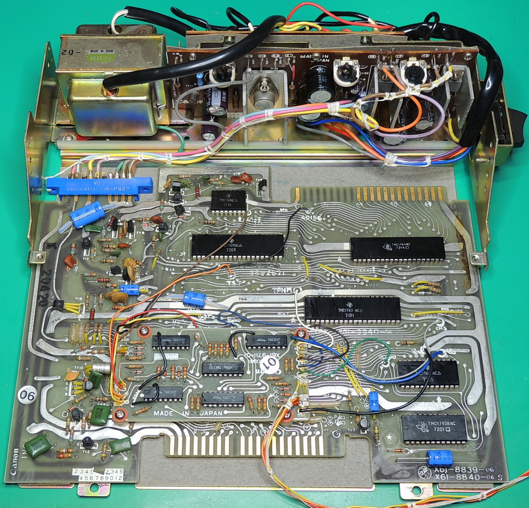
The first step of this project was to open up the unit and check for any damage from it’s recent shipping experience. The two case halves are held together by four machine screws, one on each corner. With the unit facing forward, the upper case folds up from the back and is hinged at the front edge by numerous cables.
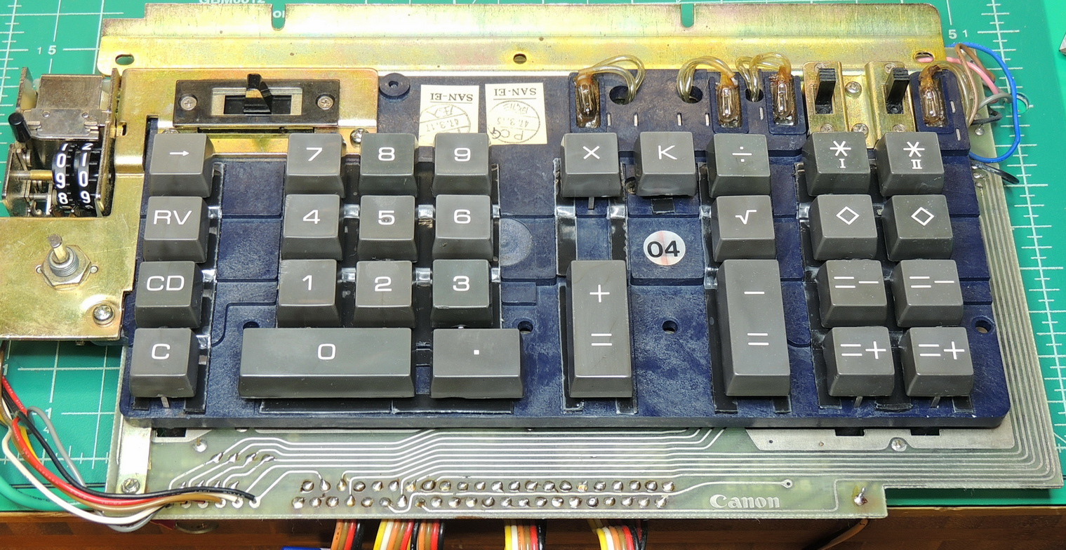
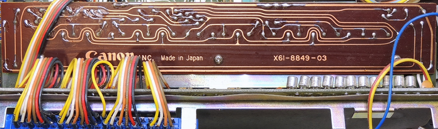
In earlier revisions of the 650 calculator, the top case and keypad could be easily separated using the provided connectors. This revision has the small daughter board with three soldered wires connecting the board to the keypad assembly. I found it easiest to unsolder the wires from the keypad to separate the two halves.
Other than being a bit dirty inside, I didn’t see any physical damage to the tubes and boards. I did pull out about two dozen small plastic shards from the inside. Most of the shards were from the epoxy used to originally join the case pieces together.
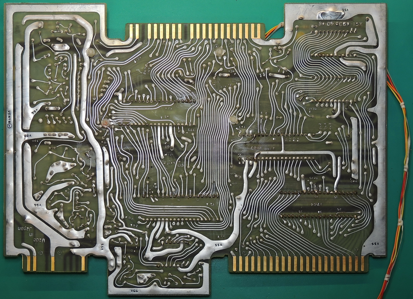
All the capacitors checked out fair but not great when tested in-circuit. After 51 years of use they were definitely due for replacement, so a list was made and an order placed. The power supply uses mainly radial format capacitors, while the other boards use only axial format capacitors.
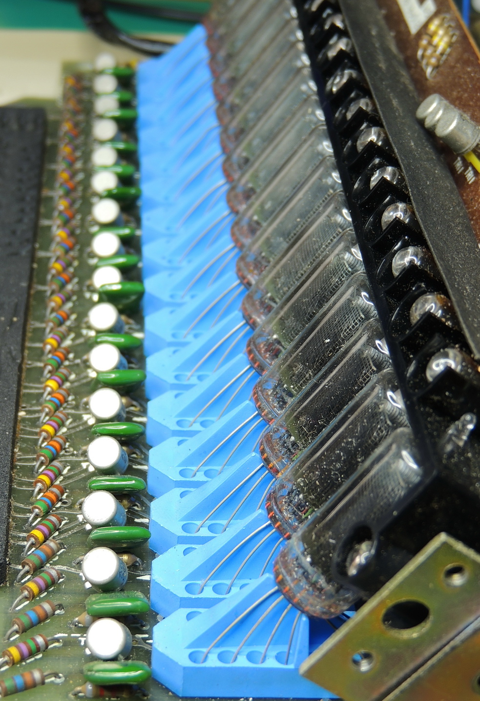
The calculator uses Hitachi CD81 miniature Nixie tubes along with a striking sky blue wire separator and tube holder fixture. There are 16 Nixie tubes and 21 Neon lamp indicator displays.
While waiting for parts and materials to arrive it was now time to disassemble the unit and clean it inside and out.
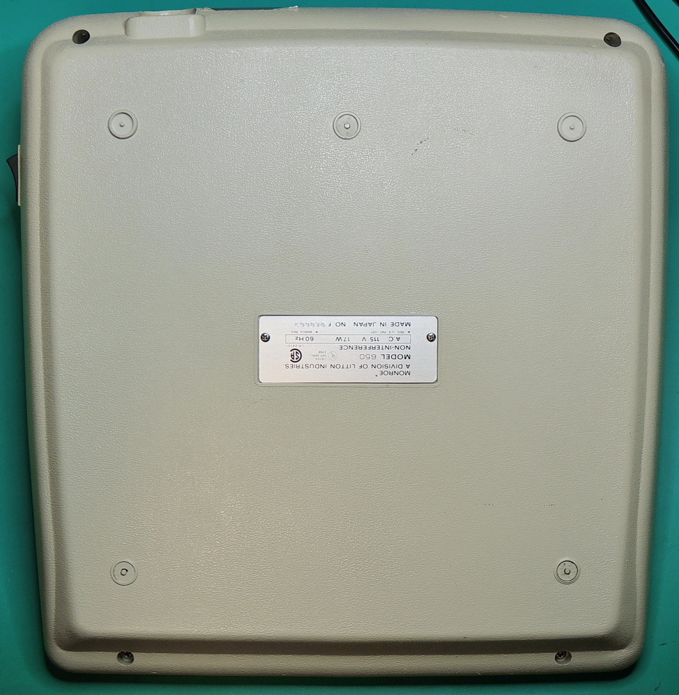
The calculator measures 12 ⅜ x 12 x 3 ⅟₄ ” (31.4 x 30.5 x 8.26 cm) which is much larger than the calculators that I have previously worked on.
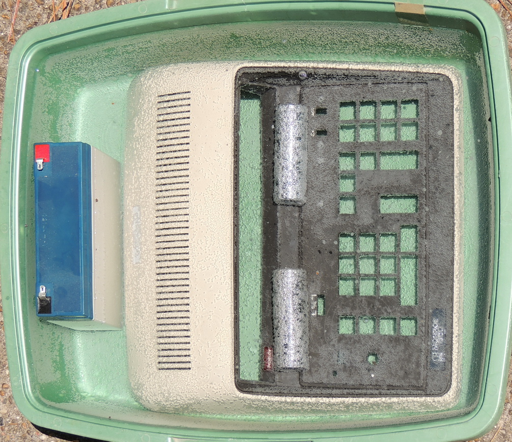
So I had to make a deal with our house cat for some catnip in exchange for borrowing her kitty-litter container. Yes, I did clean it out well before using it for the retrobright procedure, which required two gallons of 12% hydrogen peroxide solution. Also the battery is not fully in the solution, and was used to displace some of the liquid to raise the overall level. Heavy chromed sockets were used to keep the case from floating due to all the bubbles. In full sunlight each case halve took around 4 hours to complete.
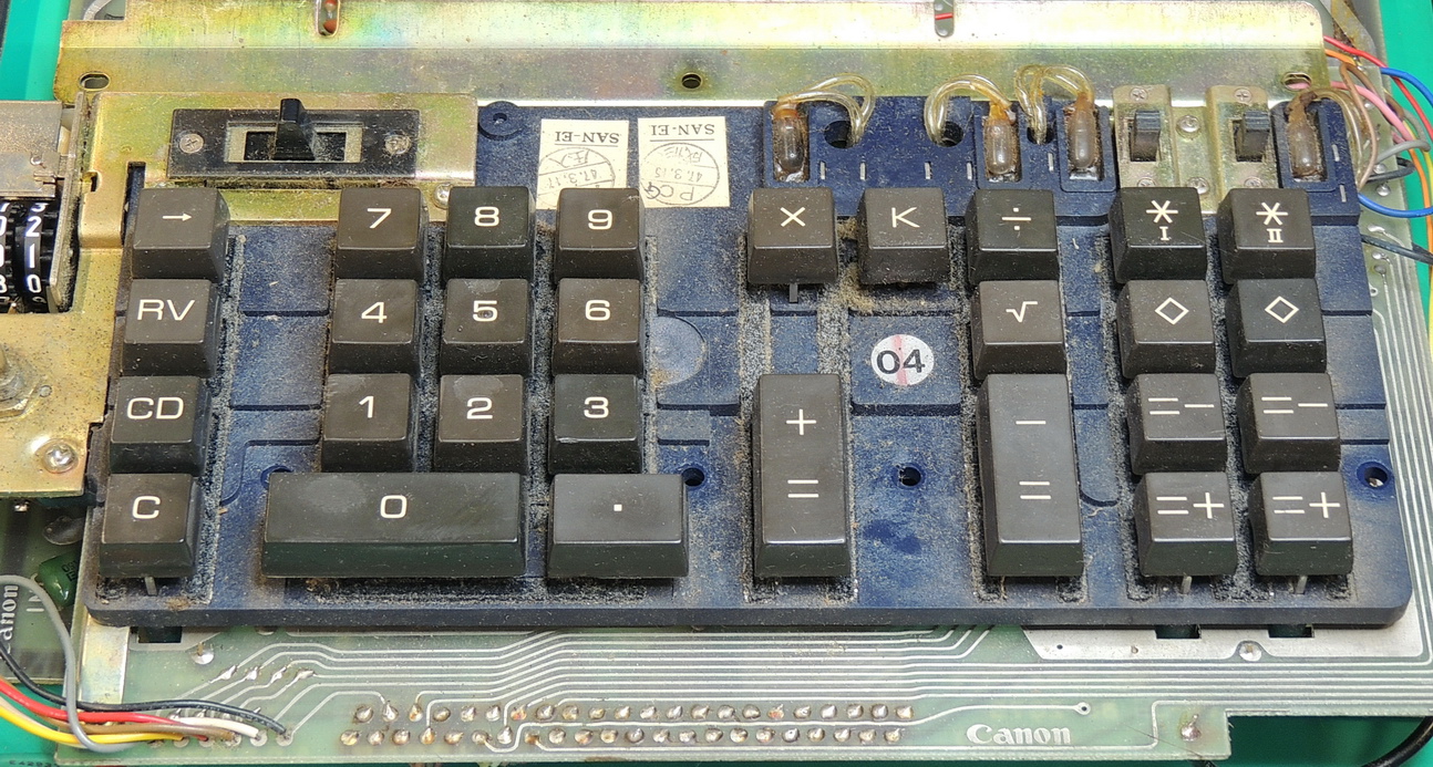
The keypad assembly took the longest to refurbish. The foam pads below the keys had completely disintegrated leaving a gooey adhesive tape attached to the keypad frame. All the keys were removed to facilitate cleanup.
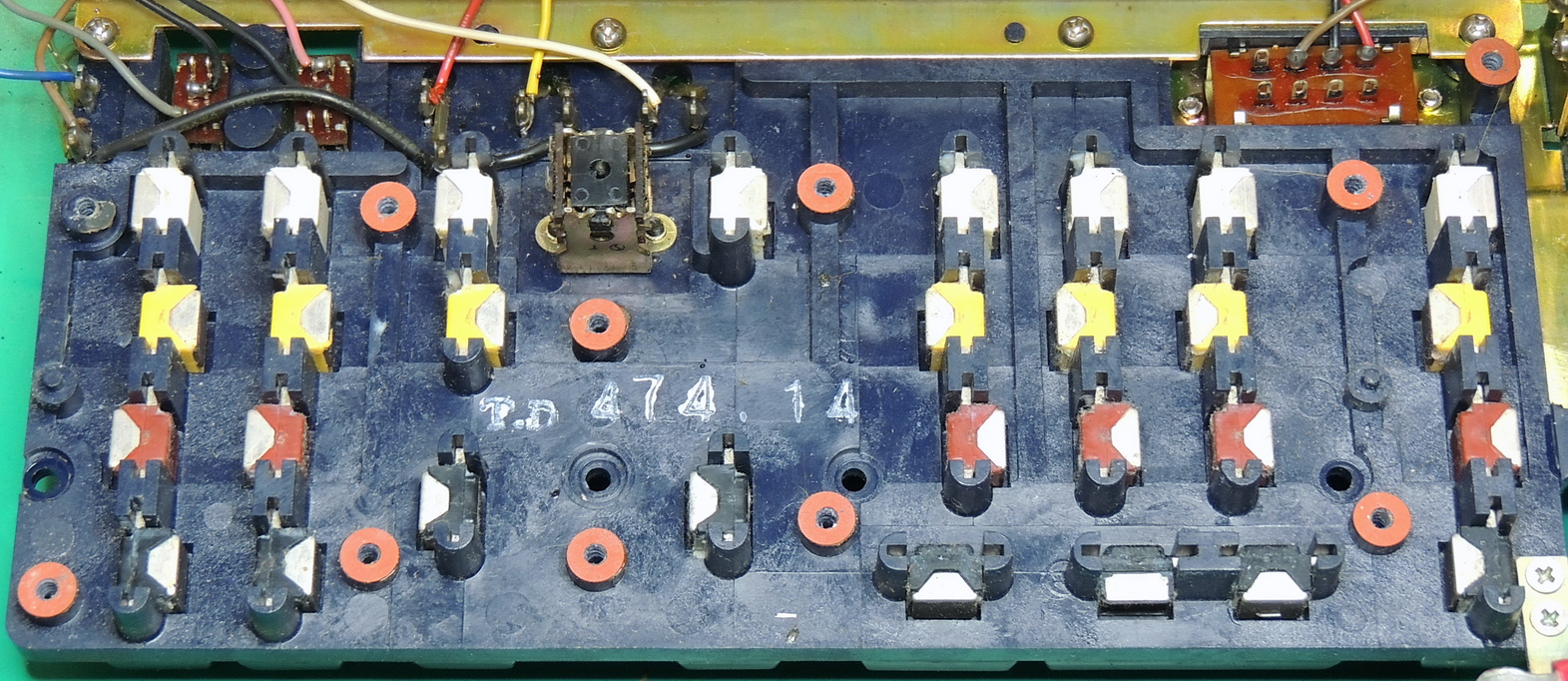
The keypad is a magnet / reed-switch type and has a smooth feel when cleaned up. Of special note, all of the keys had a light glue applied when originally assembled and take quite a bit of force to begin to break them free. Once the initial movement to break the glue had started, I switched to a small flat blade screwdriver to separate the keycap from the metal posts by alternating front to back positions to gently separate the cap. The metal posts and magnet assemblies will generally fall out the back side of the frame once the cap and spring are removed. Use caution not to let the assembly drop too far, as this may dislodge the magnets, which I managed to do just once.
The keycap for the constant “K” key is not necessary to remove, and I ended up breaking the cap from the glued post, but it was easy to epoxy back on.
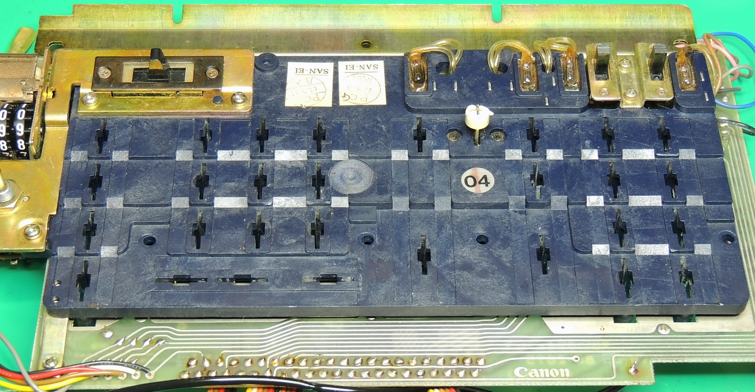
All the slide switches were cleaned with DeoxIT D5 contact cleaner before reassembly. The keypress counter and decimal point switch were both in great condition and just needed some external cleaning.

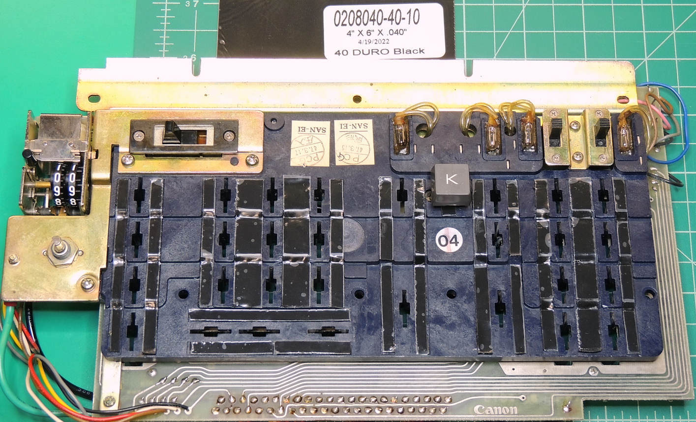
Instead of using a foam strip for the keycap stops again, I ended up using some 0.040″ 40 durometer (extra soft) Sorbothane, Polyurethane Rubber Sheet. My initial testing showed that this material did an excellent job of cushioning the keycap press and was nearly noise free. The only unknown is how long will it last.
After a good scrubbing with my favorite citrus based cleaner and a toothbrush, the keys were then soaked in some previously used 12% hydrogen peroxide solution overnight before re-installation.
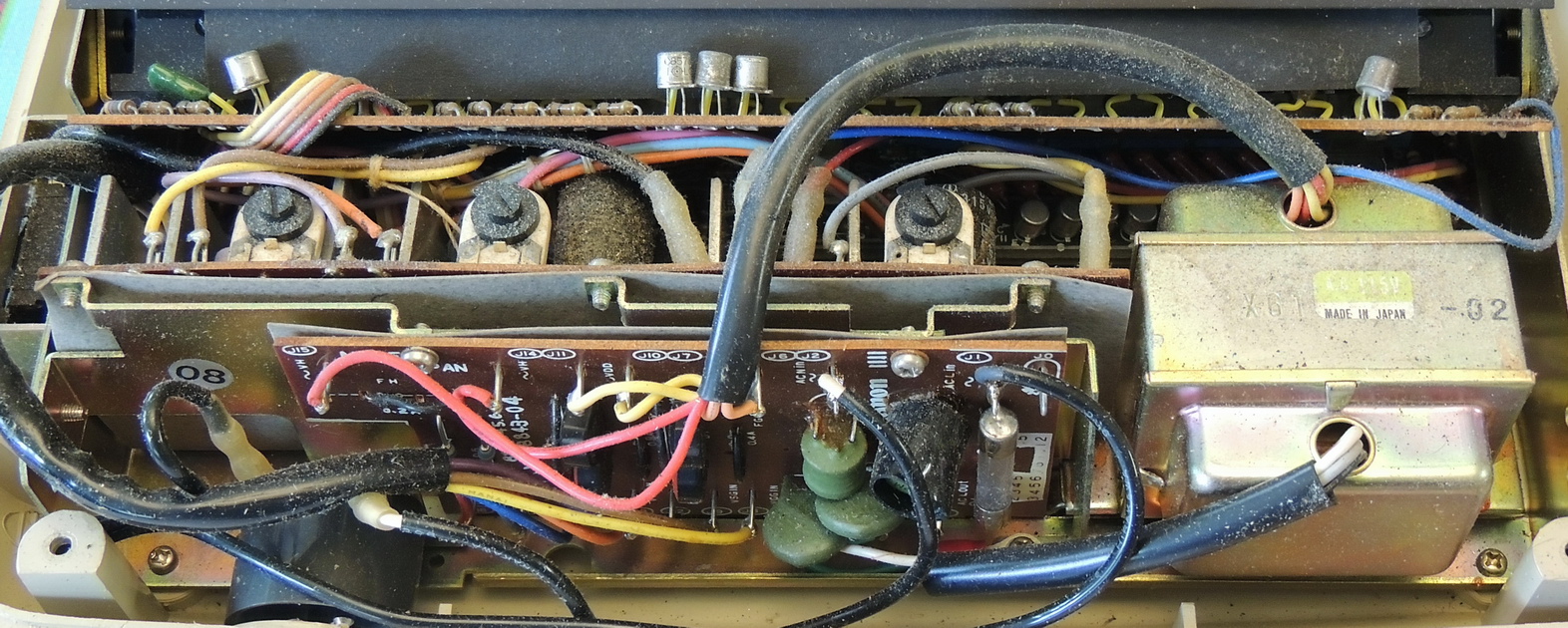
The replacement capacitors arrived ahead of schedule, so it was time to tackle the power supply section of the calculator.
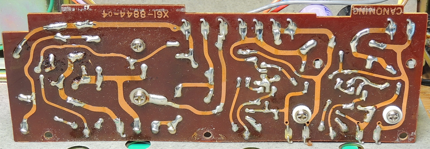
The DC regulator board is a single sided phenolic composition with the component leads bent over on the traces and then hand soldered. The replacement electrolytic capacitors went well and were mostly smaller than the originals.
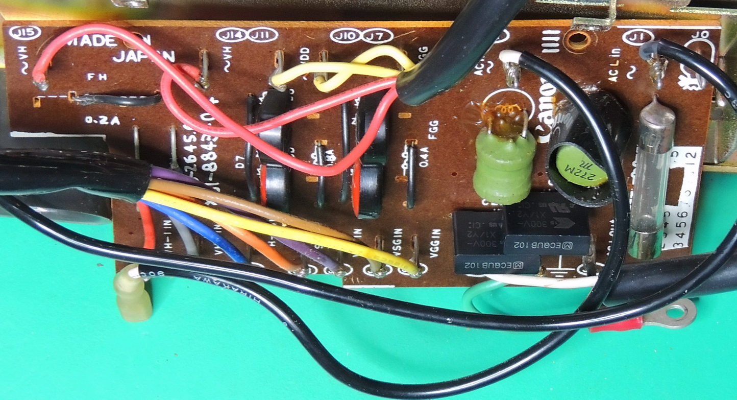
On the power supply AC rectifier board I replaced the original ceramic 1 nF AC line to ground capacitors with some new X1/Y2 safety capacitors of the same rating. I did find one cracked trace that looked to have happened recently in shipping, which was quickly fixed by reflowing some new solder.
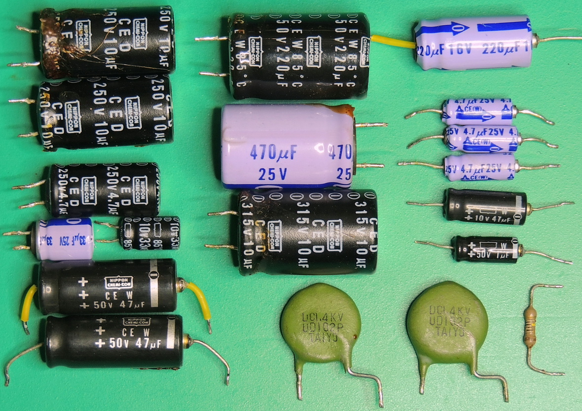
Now that all the electrolytic capacitors had been replaced, I took the time to re-lace two of the wiring harnesses before starting reassembly.
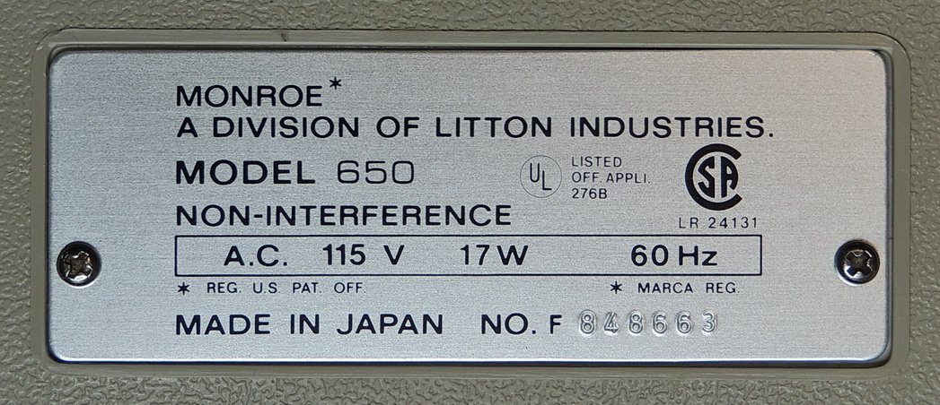
The Monroe 650 calculator is internally a slightly different featured version of the Canon Canola L163 calculator. The 650 was built specifically for Litton Monroe by Canon of Japan, with just enough changes in features to differentiate the two models. The 650 lacks the percentage function of the L163, but gains additional memory functions, and is faster.
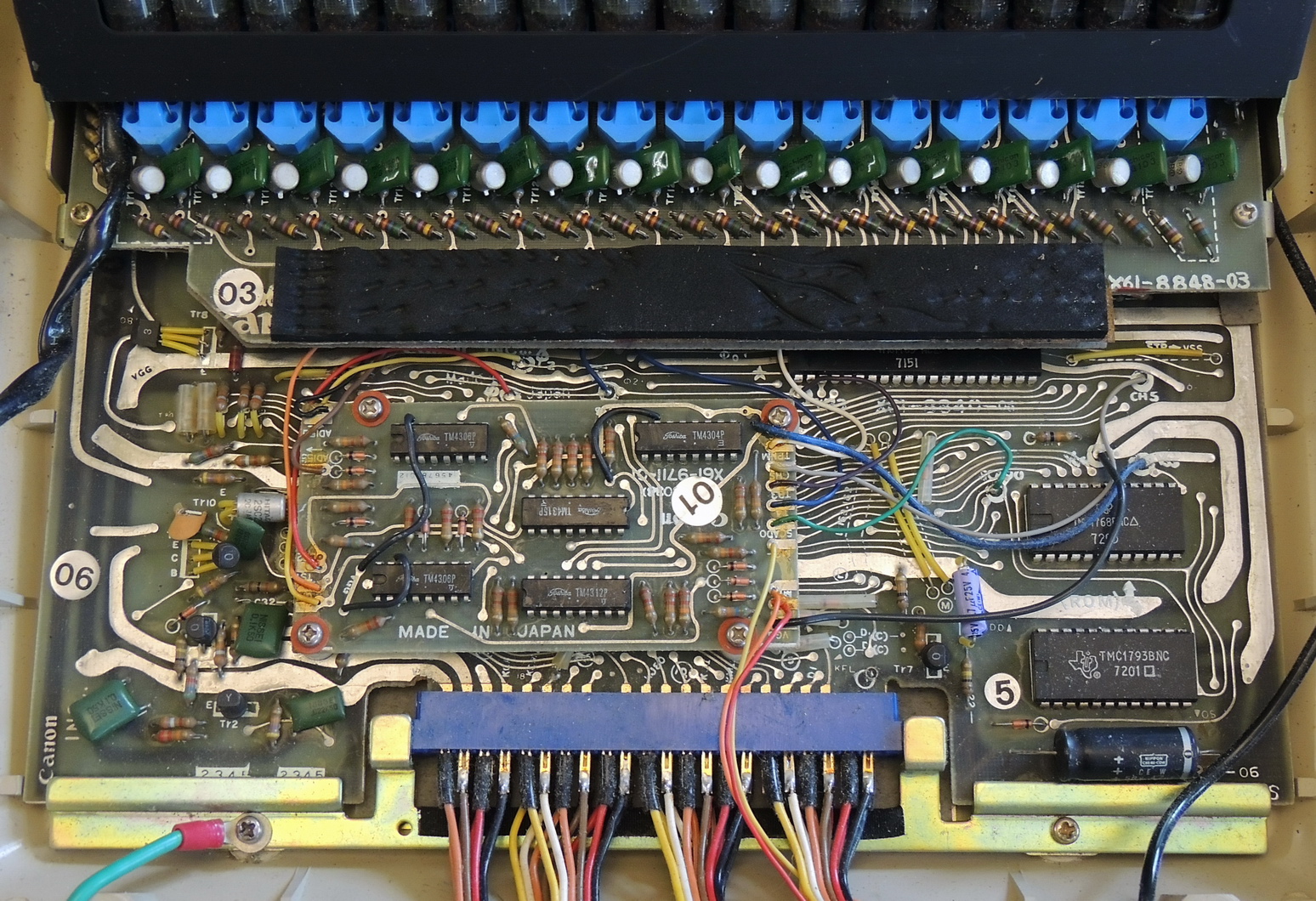
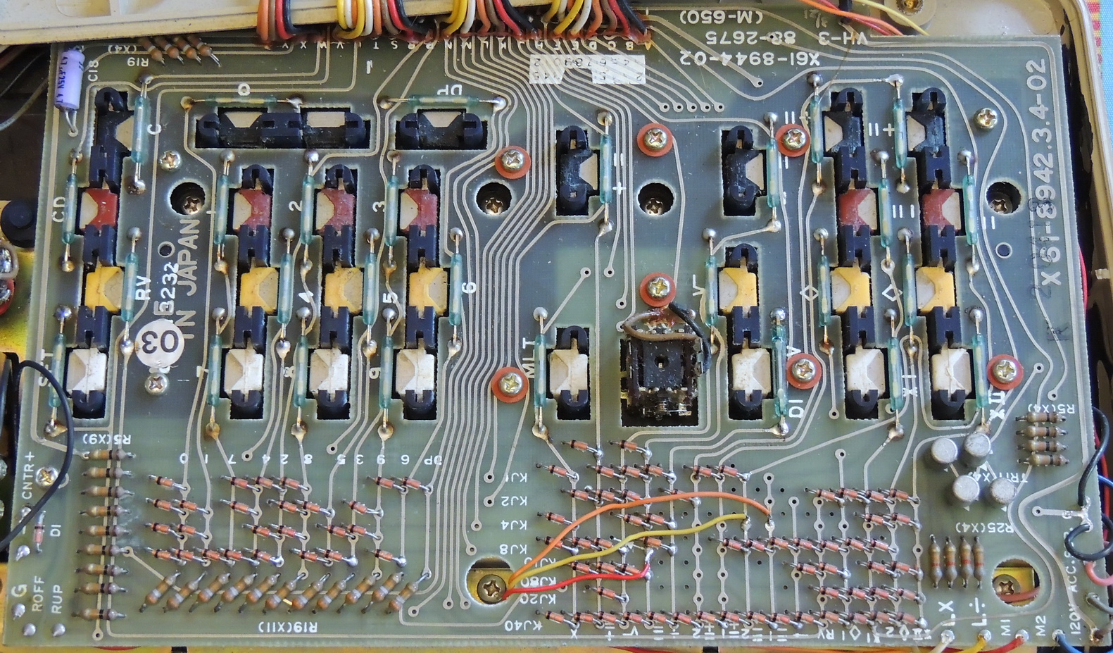
The 650 uses a Texas Instrument chipset is comprised of seven IC’s using 10-micron process, 1‑metal P channel MOS transistors.
The chipset includes the TMC1766 keypad interface, TMC1763 decimal point selection interface and output to the TMC1761 display shift register, TMC1764 display anode cathode and indicator output, the TMC1765 arithmetic chip, TMC1768 and TMC1793 program ROM’s for storing plurality of microprograms.
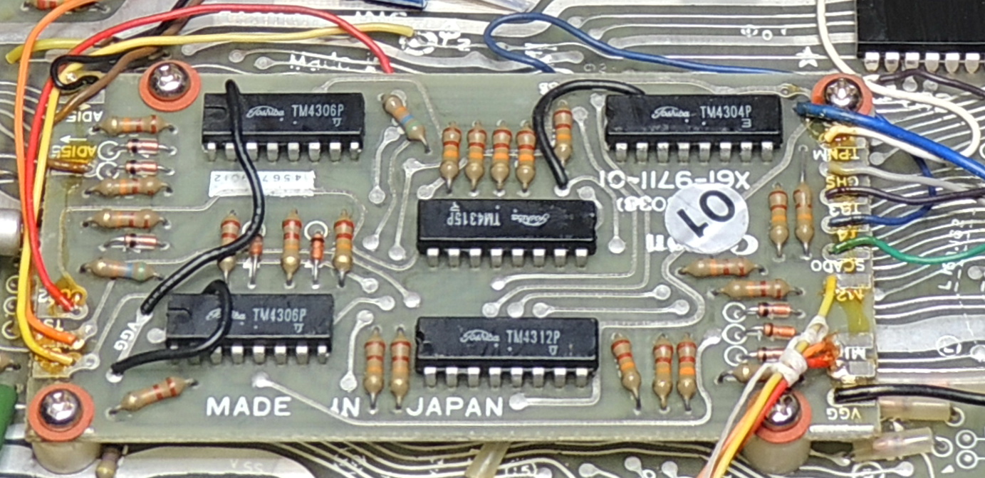

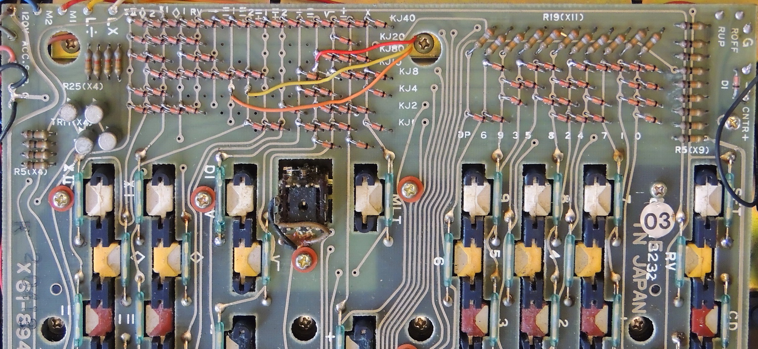
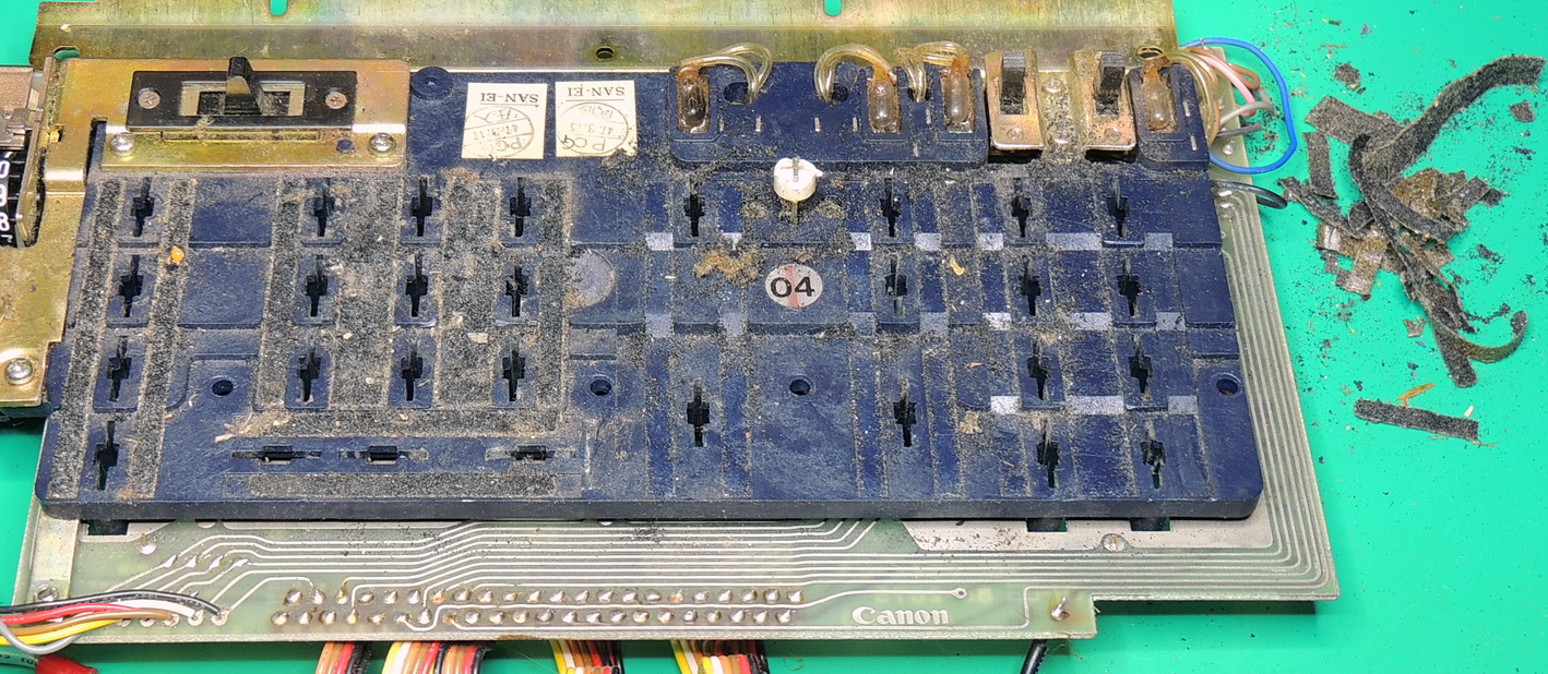
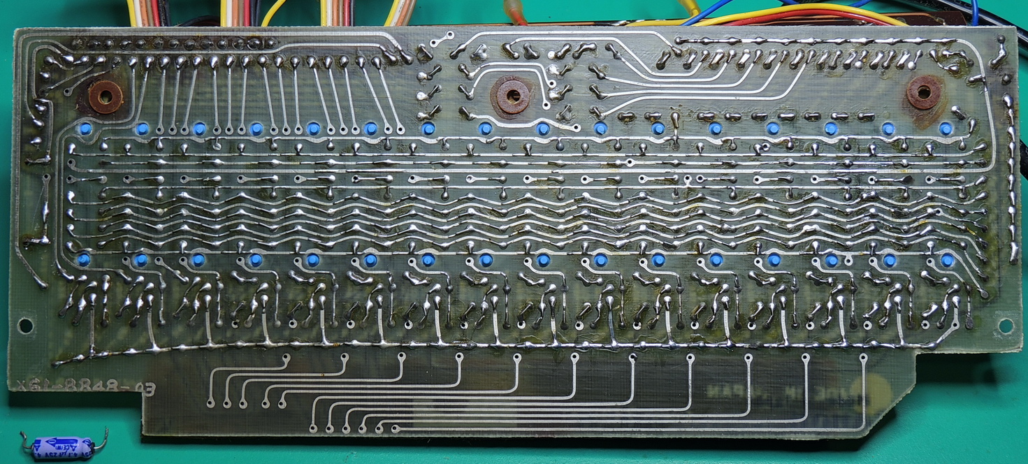
Earlier revisions of the 650 did not have the small daughter board located above the keypad connector. This additional seems to be related to the memory functions of the calculator and has a set of three wires attached to the keypad diode matrix. The wires attach to the (=-1), (=-2), and the (=-) diode matrix pads. There are five Toshiba TM43xx logic IC’s on the board along with twenty two 22K Ohm pull-up resistors, two 56k Ohm resistors, eight diodes, and a dozen wires that connect to the main circuit board.
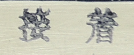
Based on the electronic component date codes and manufacturing stamps, this calculator was built in April of 1972. Hopefully Google Translate did a good job on the city / region / process translation. Any corrections would be appreciated.
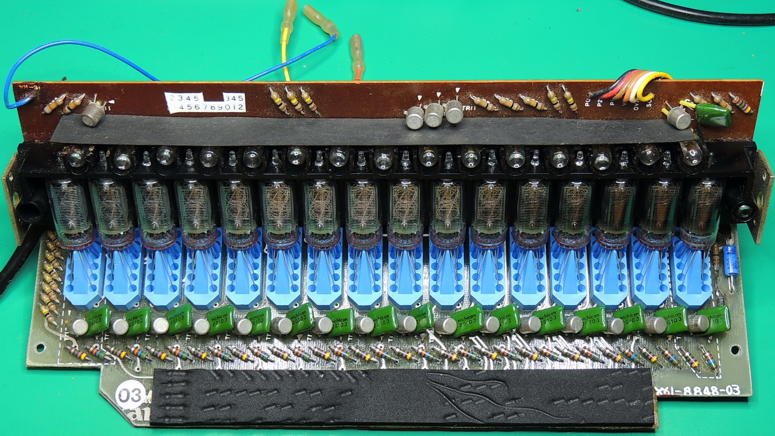
The Nixie tube display assembly is connected to the main board by an edge connector cable, and to the power supply with three individual power wires that plug-in to terminals on the high voltage regulator section.
The keypad diode matrix rests on the black foam pad located on the front edge of the display assembly. At first I was concerned that the material may have deteriorated from age, but the foam is still very resilient and I performed several high resistance checks on different areas of the foam with no issues, so no need to replace it.
It was finally time to power up the unit, so I attached several of my multimeters to the different DC outputs of the power supply before turning it on.
Most of the voltages were very close to where they needed to be with the exception of the 215 volt VH‑1 terminal which I could not adjust down to the correct voltage. The culprit ended up being the 130K Ohm resistor in the adjustment section of the HV regulator.
After replacing the resistor all the voltages were nominal, and I had a display of 0 on the calculator.
After a thorough check of all the keys, switches, and functions everything was working great.
Here are some power readings I measured at 121 volts AC input:
16.7 Watts at 0.85 Power factor — Full load 16 digits displaying 8’s and most indicators on.
12.5 Watts at 0.81 Power factor — Idle, only the least significant digit “0.” and no extra indicators on.
I spent a good part of an afternoon repairing the damaged upper case. I used some J‑B Weld 50139 black plastic bonder epoxy, which was a good match to the original epoxy used by Cannon. I cleaned up the excess epoxy that squeezed out on viewable sections using 99.9% isopropyl alcohol.
After sitting overnight I used some of my Plexus plastic cleaner, protectant, and polish on all the outside plastic parts of the case, including the keys, and display window.
A website that was a great help on the electronics side of the restoration has been the Madrona Grove Website of Brent Hilpert. He has reverse engineered an early version of the Monroe 650 calculator, and has published his schematic for this calculator, and many others also.
So now this is my favorite calculator in my small collection. It has taken over the position from the Burroughs C 3207, 14 digit Nixie calculator.
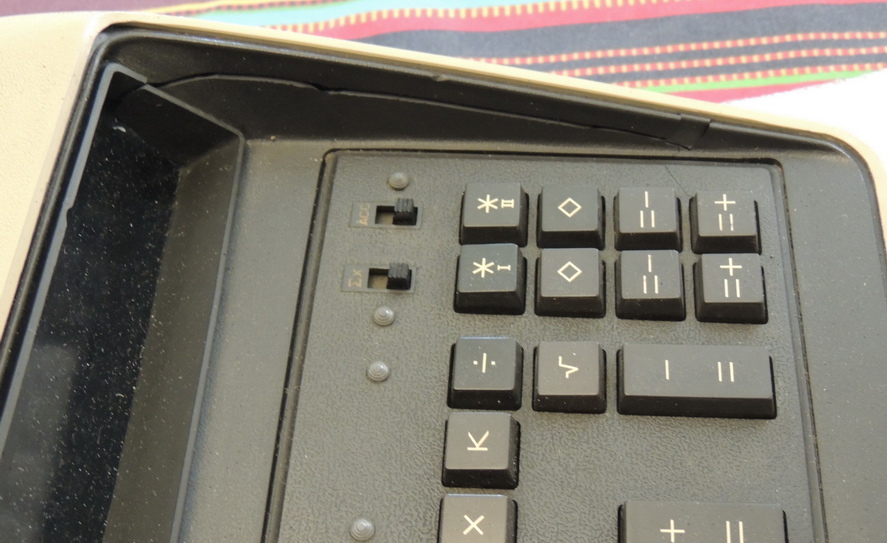
What’s not to like? It has two more beautiful orange Nixie digits, an extra memory, square root function, floating point mode, an entry counter, and a backspace key. Now I just need to make a bit more room on my desk.