

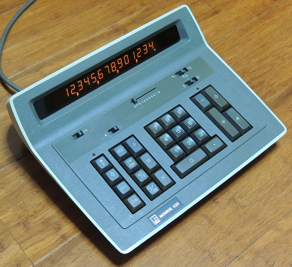
I managed to snag a Monroe 430 calculator that was in good condition and a reasonable price. The Monroe 430 is 14 digit four-function calculator with memory, percent, and a few other extras. I have worked on a model 425 and 420 in the past so I kind of knew what I was getting into, especially the lack of documentation.
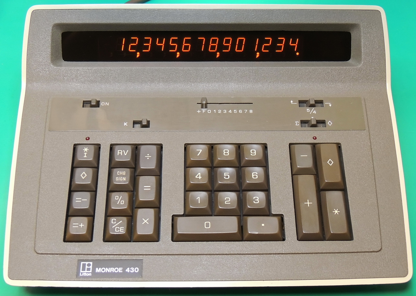
The 430 is the second from the top of the line of the Monroe 400 series of calculators, which include the 410, 415, 420, 425, 430, and the 440 models.
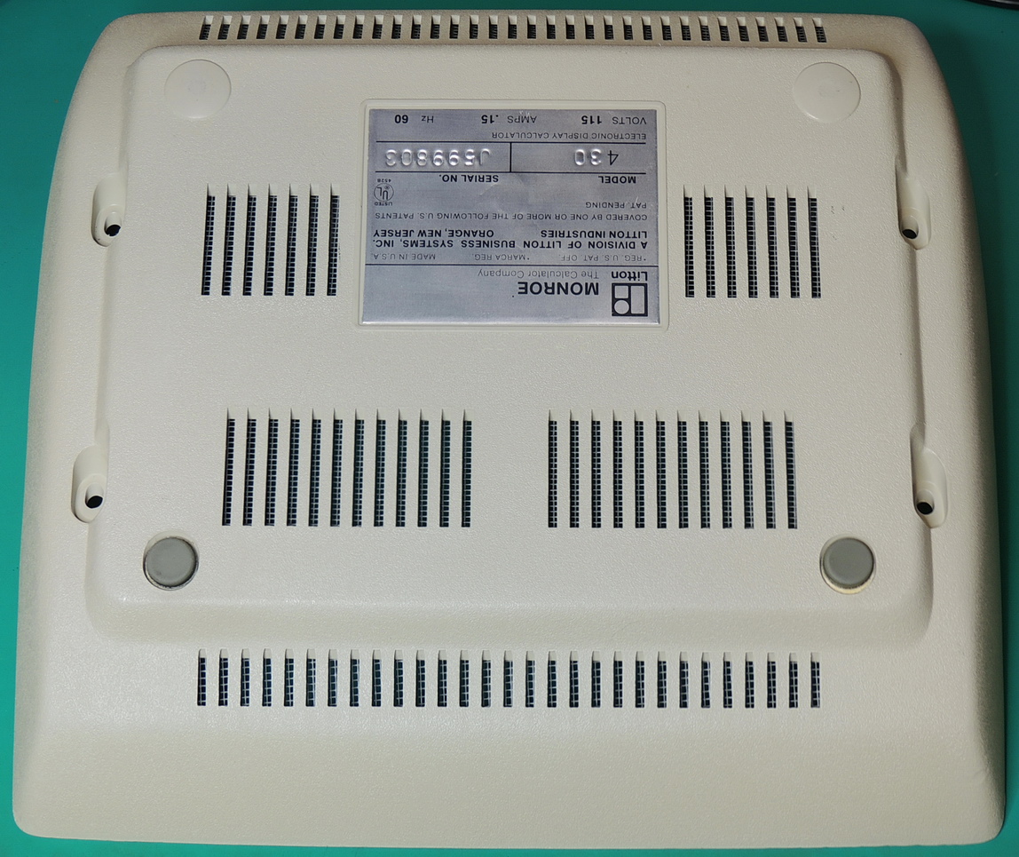
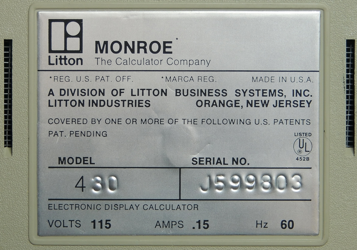
This model 430 calculator was built in late 1974, but the model was introduced in 1973. It uses the Rockwell A4541PB VLSI calculator on a chip integrated circuit.
Compared to the Monroe 425 calculator, this model adds two additional digits, selectable rounding, constant “K” selector, ∑ / ◊ selector, “RV” register swap, Change Sign, Percent, full memory control keys, and Memory LED indicator.
The lower case is held in place by four screws that when removed allow the top assembly to easily slide out. While not terribly dusty, there was a lot of loose junk inside the case which included deteriorating foam from the keypad, and hot-melt glue chunks used to secure the display module.
The display module is a Burroughs Panaplex II gas-discharge module with 14 seven segment digits, 15 decimal point / comma indicators, and a minus sign. Separate from the Panaplex module is a + — X ÷ display module that indicate the function being performed.
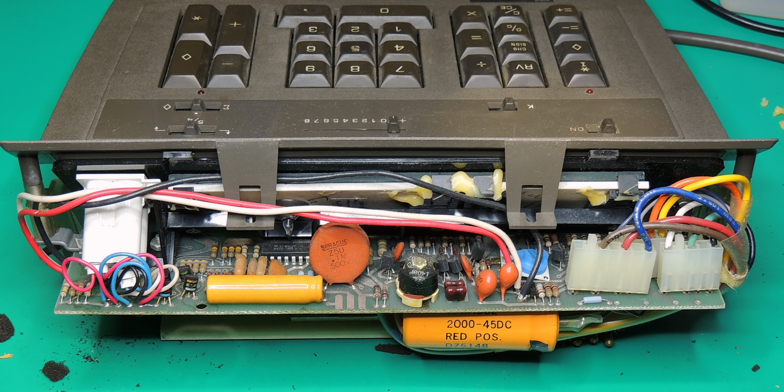
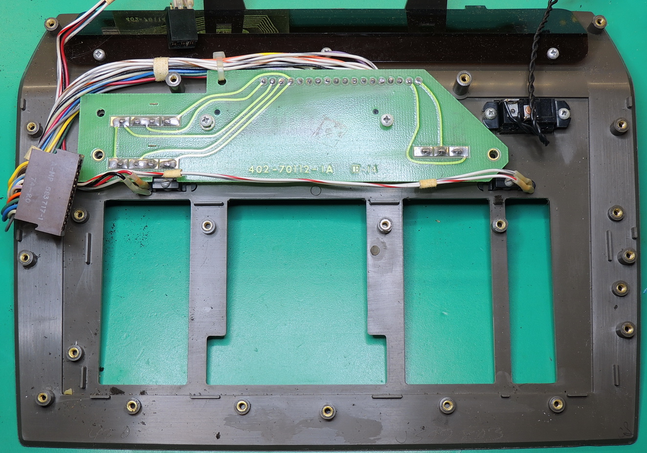
The functional parts of the calculator include five sections:
1 — Transformer and frame assembly with AC power input connector, bulk filter capacitor, and power transistor attached to frame as a heatsink.
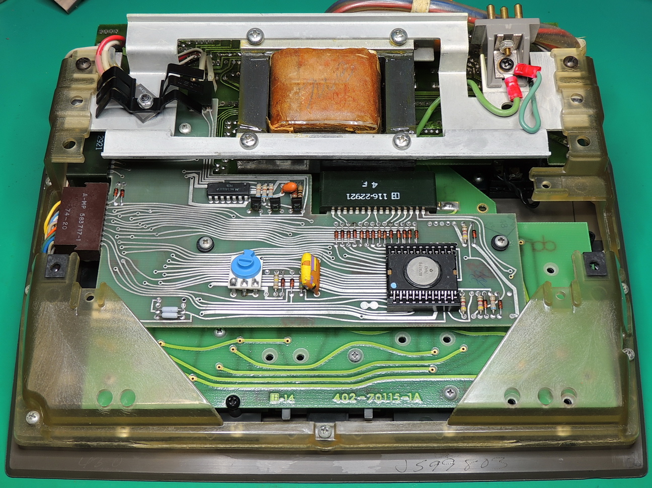
2 — Rockwell A4541PB processor and interface board
3 — Keypad assembly
4 — Front switch and decimal point slide switch board
5 — Display interface and power supply board
The brown card edge connector in the above image connects to the front switch board.
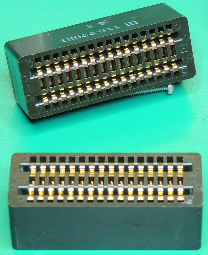
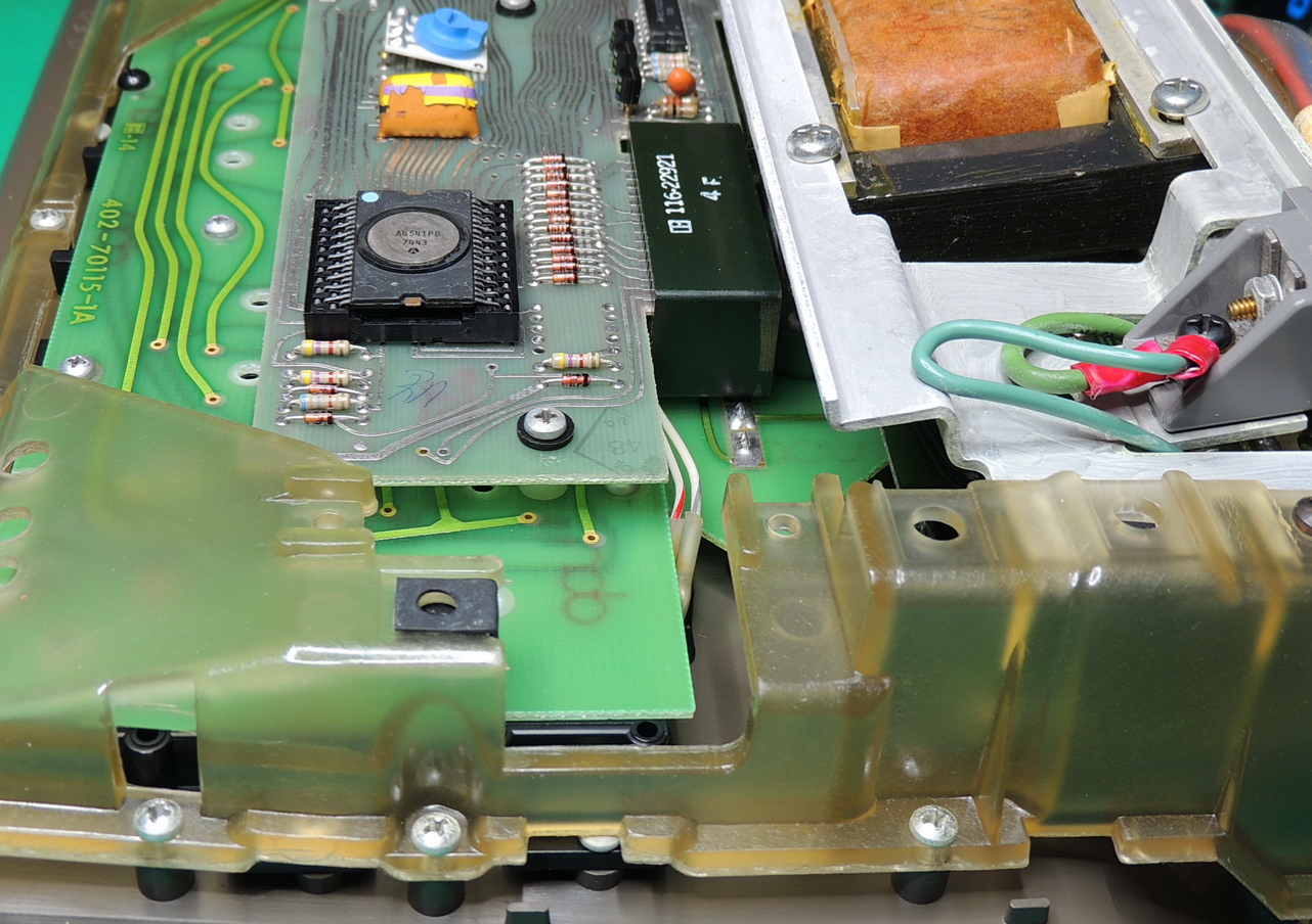
The processor / interface board is connected to the keypad assembly and the display interface / power supply board using some Litton 32 contact card edge jumper plugs.
The plugs carry signals and power between the boards.
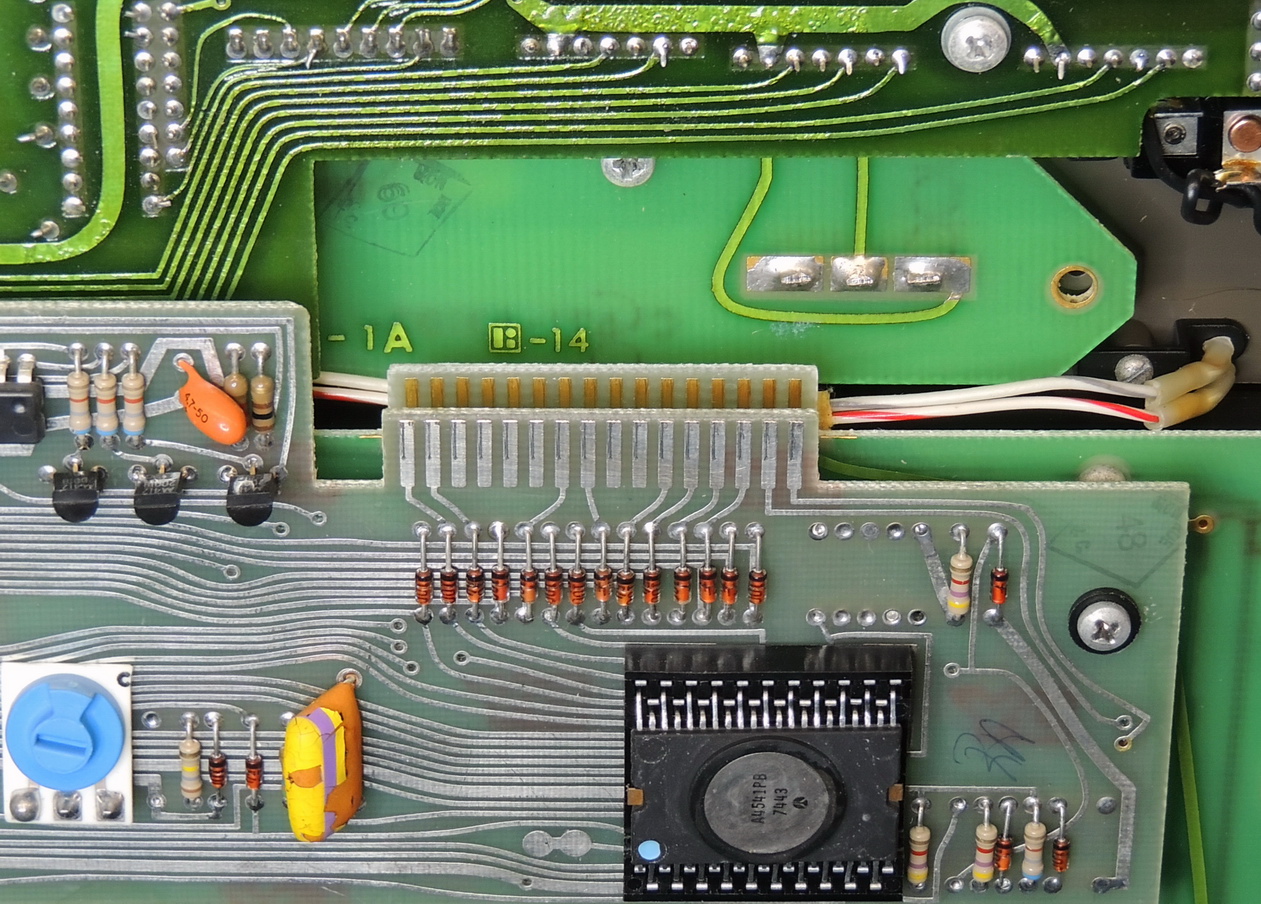
Other than the processor and connectors there is not a lot happening on the board, the MC14011CP IC is a quad 2‑input NAND gate, and there is an array of diodes for the keypad assembly signals. The front panel LED indicators are connected to the board using a keyed 6‑pin card edge connector.
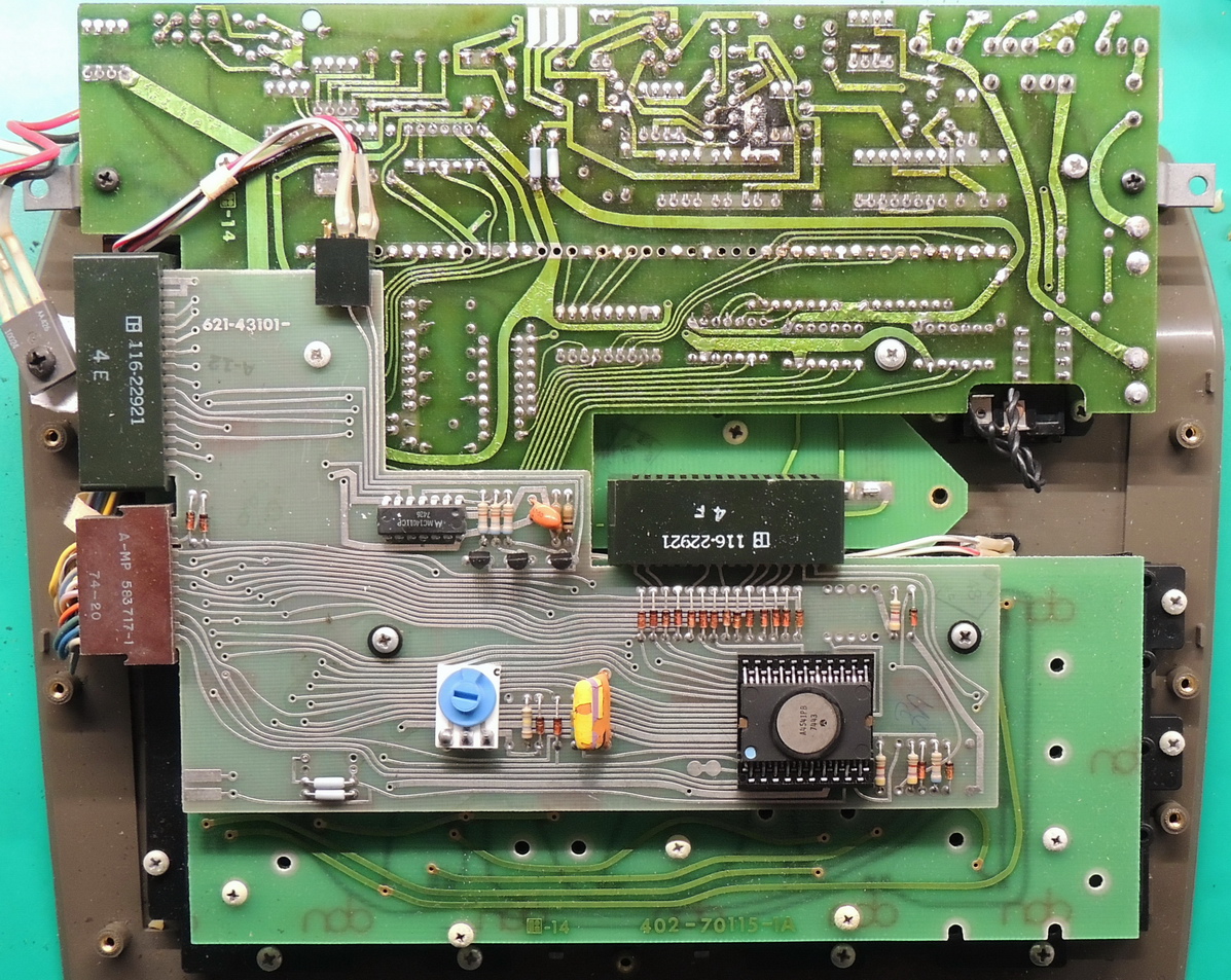
There is quite a bit more happening on the display / power supply board. This is where the first repair was required.
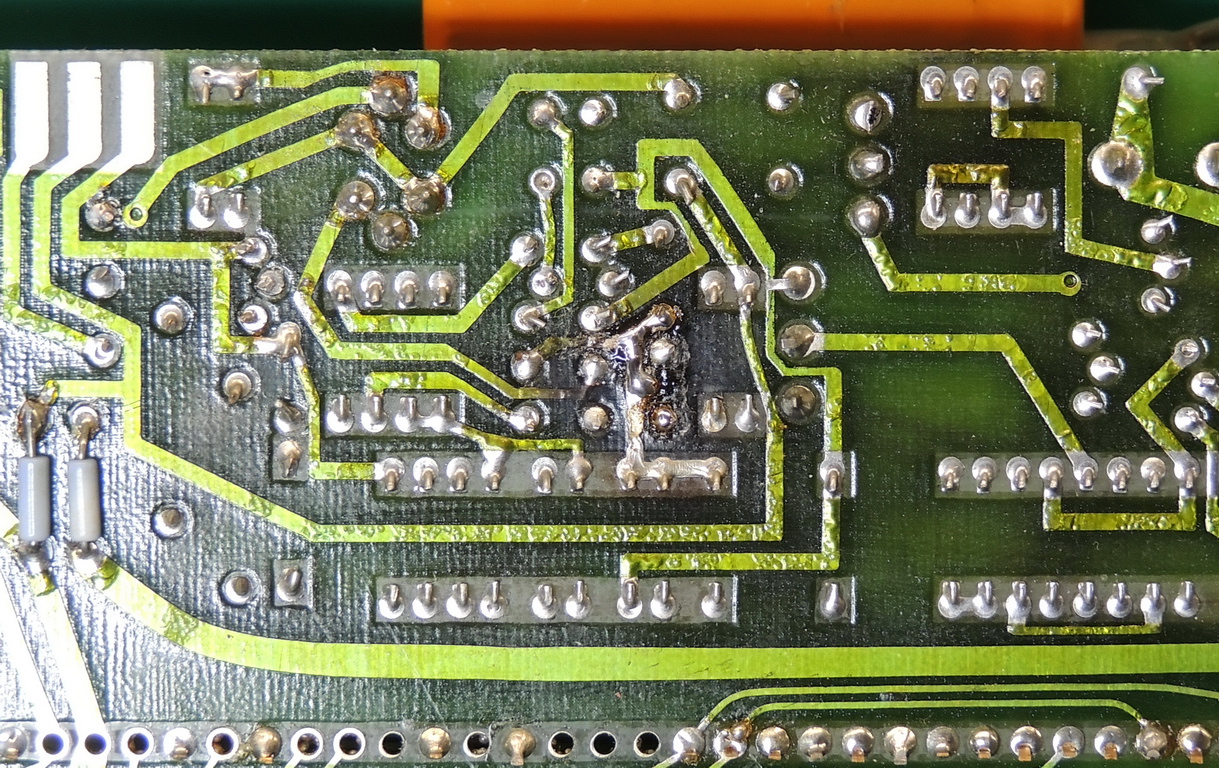
I found a discolored section of circuit board directly below a TO-92 transistor. A quick diode check with my multimeter showed no issues, so I reflowed several of the connections and added a TO-92 heatsink along with some thermal paste to the transistor. My best guess is that this is part of the power supply and is a result of many years of operation in possibly a hot environment.
The front panel switch board provides a connection of the slide switches to the processor / interface board. It includes the sliding contacts for the 11 position decimal point slide switch, and the three larger slide switches not including the power switch which has a separate connector.
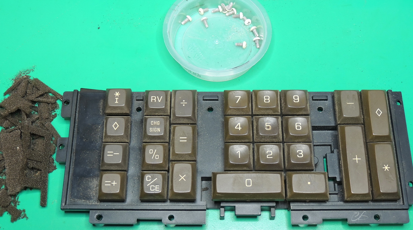
The keypad was in the worst condition, and ended up needing 9 key-switches replaced. The foam around the key caps was very deteriorated and was either a fine powder or larger chunks.
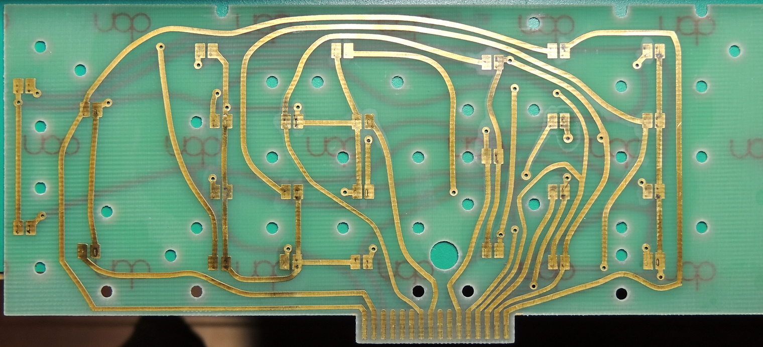

The circuit board that interfaces to the key-switch contacts had a lot of discoloration around the contact pad areas. I used a polymer eraser to remove most of the tarnish and then some DeoxIT D5 contact cleaner to complete the process.
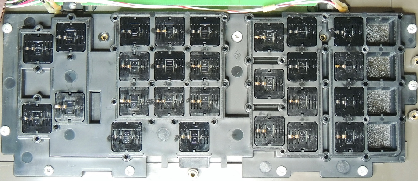
Even after cleaning the contacts of the key-switch modules quite a few of them were still non functional. There were also some intermittent modules that worked for a while but then suddenly stopped working. The assembly with it’s 13 screws was probably disassembled and re-assembled a dozen times before everything was stable.
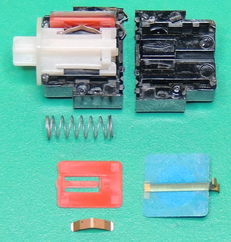
I decided to disassemble a couple of the key-switch modules to see what the failure point might be. When the switch plunger is depressed a metal spring presses on the red plastic finger which in turn presses a metal strip into contact with a stationary plate contact.
If the blue contact assembly is pressed together using light finger pressure a good contact is made, but using the flat spring and red contact finger there is no switch closure.
I might try some future modifications experimenting with the bad contacts, but for now the calculator is working, which was the main goal.
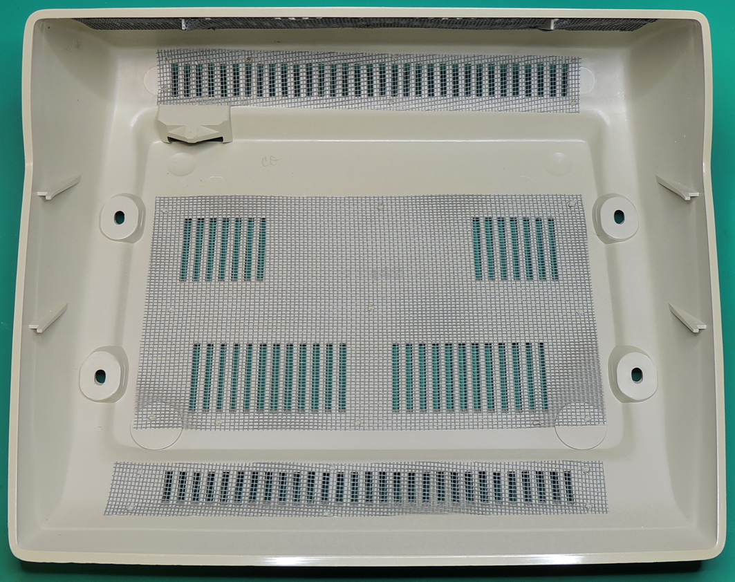
Once again I used my standard RetroBrite procedure on the lower case shell to reduce the yellowing. The case is much larger than the model 425 and required a medium sized container and two gallons of 12% hydrogen peroxide solution to completely submerge the entire case, which was left in the solution under a sunny sky for 7 hours.
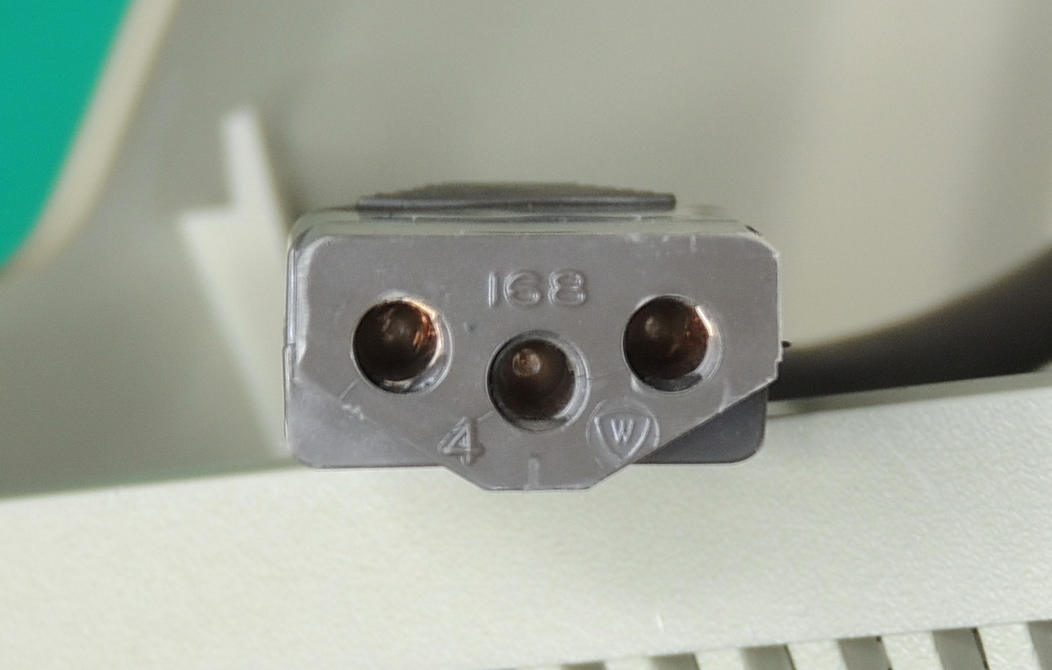
The Monroe 430 uses the same 115 volt power cord as the model 425 calculator. The end is marked with a 168, which I am assuming is the plug type.
The calculator has been working well for the past several days, with no overheating issues or additional key-switch failures.
In my opinion it is a great looking calculator, and I appreciate the extra digits and features on this model, especially the memory.
I did end up replacing both of the electrolytic capacitors in this unit, but left all the dipped tantalum capacitors in place.
I would like to find a users manual for this model as I am interested in the uses for the accumulation selector switch.
I just got one, wonderful work, the only issus I have is key 5 not working. If you got a user manual or schematics will be greatly appreciated.
Thanks
Ivan…