

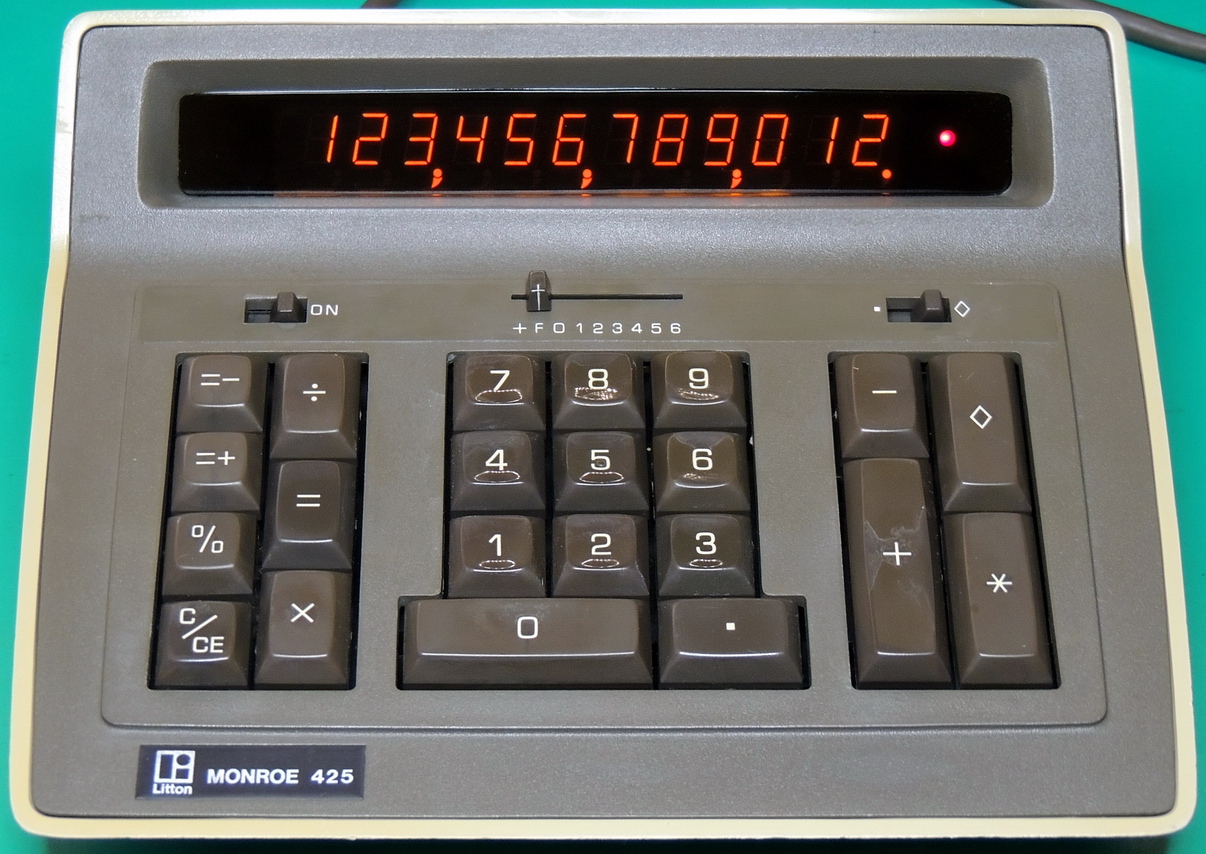
It wasn’t the exact calculator that I was looking for, but the purchase was well worth the price paid for it. The model 425 from Litton Monroe is a 12 digit Panaplex display with memory calculator.
Luckily the calculator arrived for the most part undamaged. The seller did a really poor job with packing the unit and the front panel was popped out of the back case when it arrived.
I was able to loosen the four case screws and the front panel went back to it’s normal location with a bit of persuasion.

After making sure that nothing was permanently damaged from shipping I opened the case to see what was inside. The only thing that seemed out of place was inductor coil L3, which was hanging over the edge of the circuit board by it’s leads. There was quite a bit of lint and foam debris floating around, but I somewhat expected that from the age of this calculator.

The open cell foam behind the keypad had mostly disintegrated due to it’s age and had to be removed along with it’s own accumulation of lint. I ended up completely removing the keypad assembly to get at the fine foam dust that had settled between the key modules.

I used some DeoxIT D5 contact cleaner to clean up the key contacts and circuit board contact traces, along with the card edge connector for the front panel switches.


The main calculator IC is a General Instruments 177D and is supported with an ITT 50007 and a Motorola 50008 IC. All of the IC’s are dated around mid 1974, which leads me to believe that this unit was built in late 1974. The Neon gas-discharge 12 digit Panaplex II display is soldered directly to the main board along with the short power connector wiring harness.

There is a memory in-use LED attached to the right side of the display, and a separate purple wire that attaches to the power supply board (pin E9) with a clip. The rectangular cutout in the board is where the AC power switch wiring passes thru and attaches the power supply board.


There is a clear translucent frame where the power supply board, AC connector, transformer, and filter capacitor are attached. The frame also includes the four threaded clips where the bottom case is attached along with mounting holes for attaching the frame to the front panel.

Coil L3 is only attached by it’s leads and seemed out of place upon initial opening. I was able to carefully rotate it about 110 degrees which also tightened up it’s loose windings. It was then tacked in place with some ChipQuik electronic grade silicone.

Voltages on the power connector include:
-11.95 volts
-184 volts
space
-92.2 volts
-5.41 volts
-15.2 volts
Common
Electrolytic capacitors include a 2,000 uF at 35 VDC chassis mounted capacitor, and a 4 uF at 250 VDC board mounted capacitor. The 4 uF unit will be replaced with a 10 uF 250 V axial, and the chassis capacitor will get a 2,200 uF at 40 volt replacement.

There are also three tantalum capacitors on the power supply board which I replaced with units that were one step up in their voltage rating. One of the film “butterfly” capacitors in the high voltage section had most of it’s color code paint peeling off, so I replaced both with some 0.1 uF at 400 volt polyester metallized capacitors.

Buried deep under the wiring I found some jumpers for selecting the 115 or 230 volt AC line voltage setting. The measured AC secondary voltage at the full wave rectifier diodes was 18.7 VAC at a primary input voltage of 120.0 VAC.

The transformer primary is made up of two windings with a red / brown colored lead winding, and a red-white / brown-white lead winding.

Total power draw for this calculator with memory LED on and twelve 8’s on the display is 3.2 watts, and with display and memory cleared around 2.2 watts. This is quite a bit less than the ID plate rated current of 0.15 amps. My maximum current reading was 0.055 amps average at maximum load.


The power frame assembly and main circuit board assembly attach to the front panel via brass threaded inserts and screws. This is one sturdily built calculator, and I am impressed with the engineering that went into the design and construction of this model.

The molded end of the power cable even has the Monroe name embossed into it. The calculator end of the cord is a non-standard connector with three round pins and the center pin being ground. The number 168 is molded into the end of the plug. While the pin configuration is similar to a type 163 and Japanese calculator connector, the Monroe plug has two bevels making it a very odd plug.

The bottom case had some yellowing on one side from sunlight exposure, so I decided to try a retrobrite procedure to see if it could be brought back to the original color. After 20 hours of treatment I would guestimate that it improved the case to 90% of the original color. Now it is only noticeable if the unit is apart, allowing a comparison between the inside of the case to the outer area. I did use some “Plexus” plastic protectant to help prevent any future discoloration.
It looks like this calculator is heading for my wife’s work desk, as she thinks it is cute and has nice styling. Hopefully it will work well for her for a long time.
One Reply to “Monroe 425 Panaplex display calculator”