

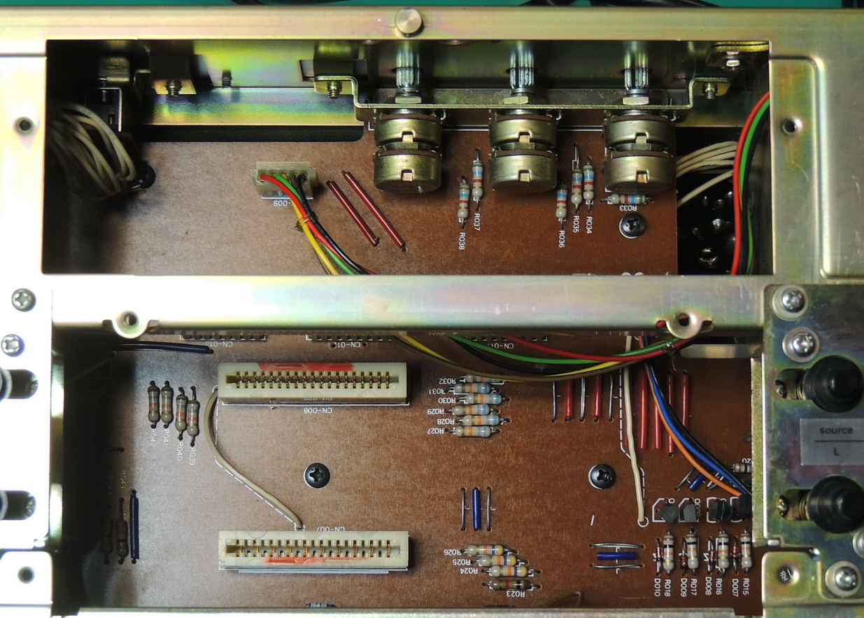
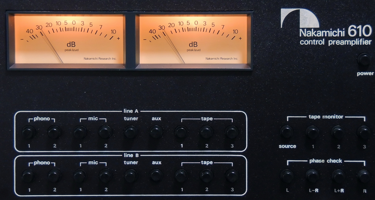
I did not take any pictures of the initial refurbishment of the Nakamichi 610 control preamplifier as it was mainly cleaning and capacitor replacement. But as soon as I thought the work on all the components of the System One rack had been completed, one of the dB meter lamps failed in the 610 preamp.
Incandescent lamps do burn out and fail over time so I thought it would be good to document the replacement procedure this time. The first step in replacing the lamps is to unplug the unit from the AC outlet. The next step is to remove the nine knobs from the front panel. The clear plastic marker behind the “master” volume knob doesn’t need to be removed. Then there are five black Philips head screws that need to be removed to free the plastic back cover. Once the back cover has been removed, there are four large Philips screws that sandwich the faceplate between the front handles and the frame that need to be removed.
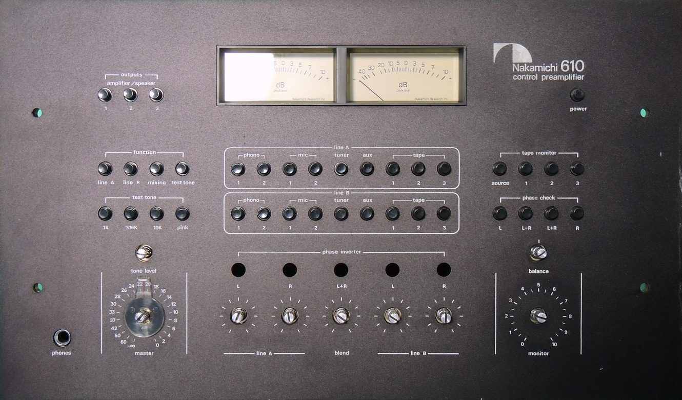
Next lift the front panel from the frame, taking care not to scrape the meter bezels in the process.
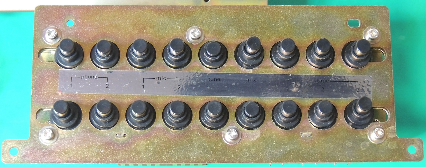
To make removing the meter assembly a bit easier, first remove the Line A and B selector switch assembly. Only four screws shown in the picture above need to be removed to extract the assembly which slides straight out.
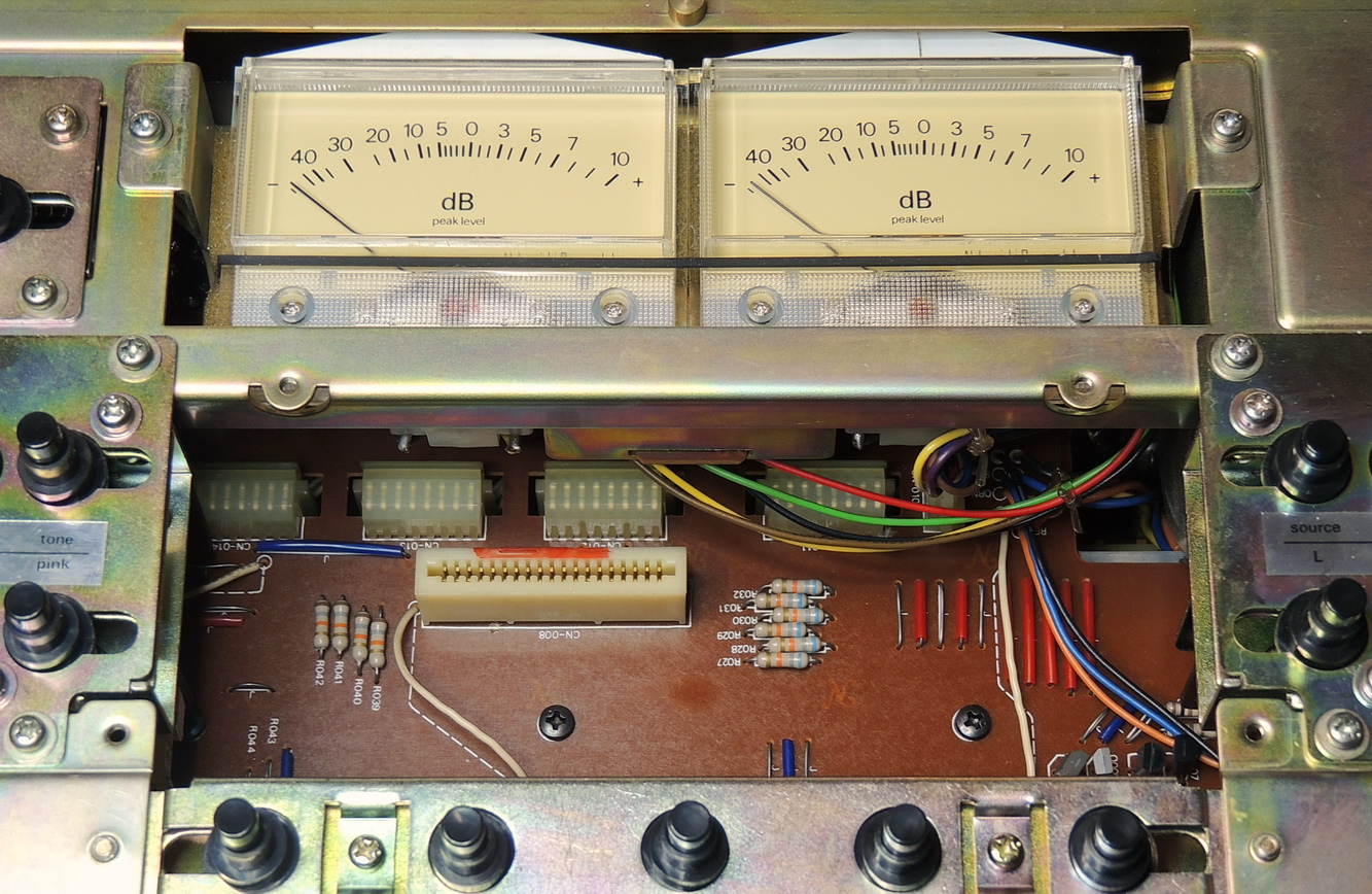
This will give better access to the meter assembly connector plug. There are two screws that hold the meter assembly in place that need to be removed. Then after unplugging the connector from the main board the meter assembly can be wiggled out carefully from the frame. I found it easier to slide the assembly down a little to clear the white lamp housings, and then tilt the assembly forward and then up to clear the frame.
Gently remove the meter bezel from the meter assembly, and place the assembly on a soft clean surface to prevent scratching the plastic meter faces.
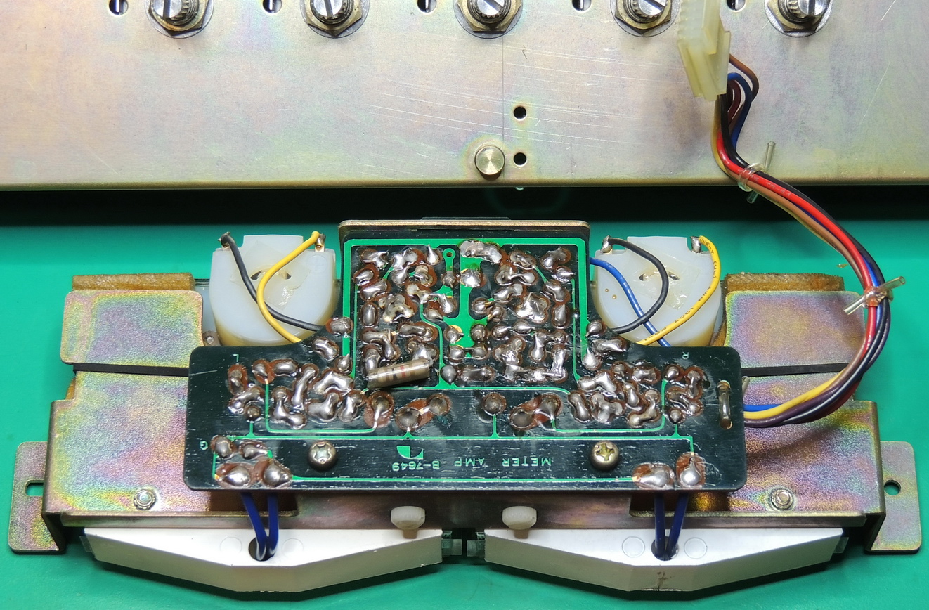
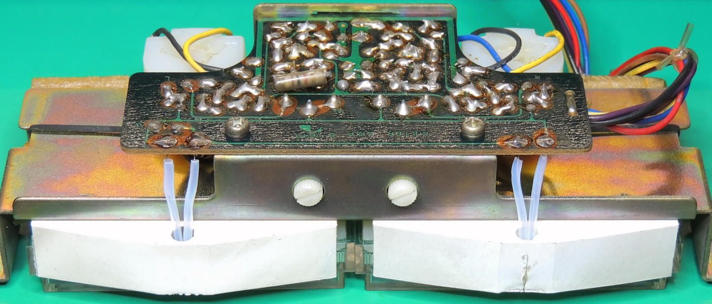
Taking care not to apply too much heat use your favorite method of solder removal to release the lamp leads from the circuit board.
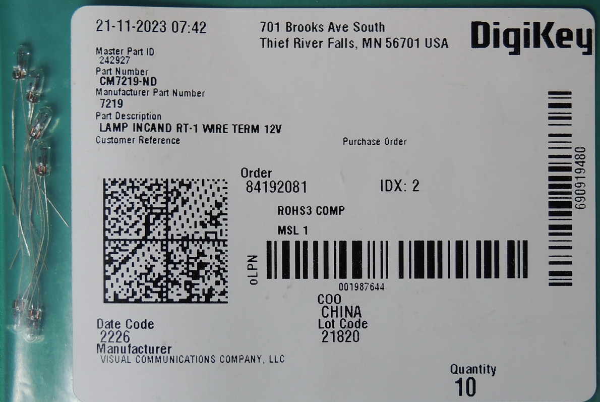
I used some 12 volt RT‑1 lamps from Visual Communications Company, LLC (VCC) that I purchased from DigiKey.com that I had in stock.
These are the same lamps that are used for part of the tuning indicators on the Nakamichi 630 Tuner / preamplifier.
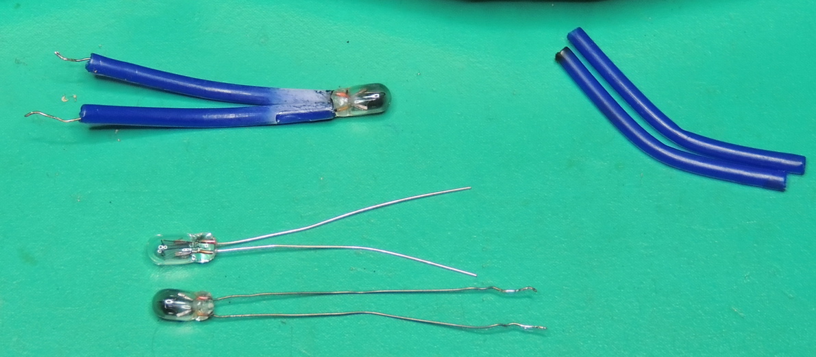
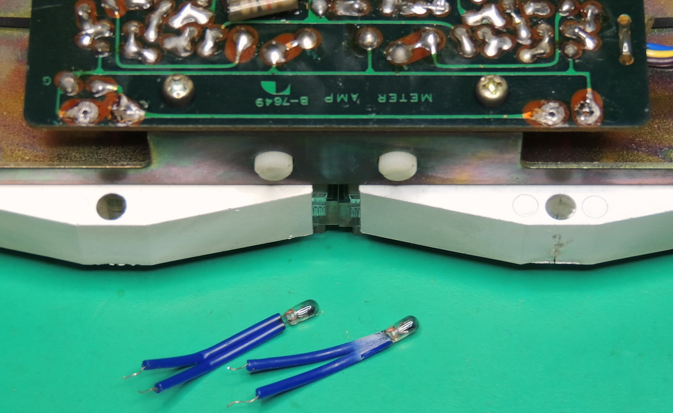
The new lamp leads are slightly shorter than the originals, but if kept straight with no kinks or bends they are just long enough to reach the solder pads. I also replaced the blue insulator tubes which had a permanent bend in them with some clear heat shrink tubes.
Before reassembling the module into the frame I recommend testing the finished assembly. I used a power supply set to 12 volts DC and a current limit set to 0.25 amps.
The negative lead was attached to the end black wire terminal, and the positive lead was attached to the purple wire terminal which was four positions in. I do recommend checking the connections before applying power to verify these are connected to the lamps.
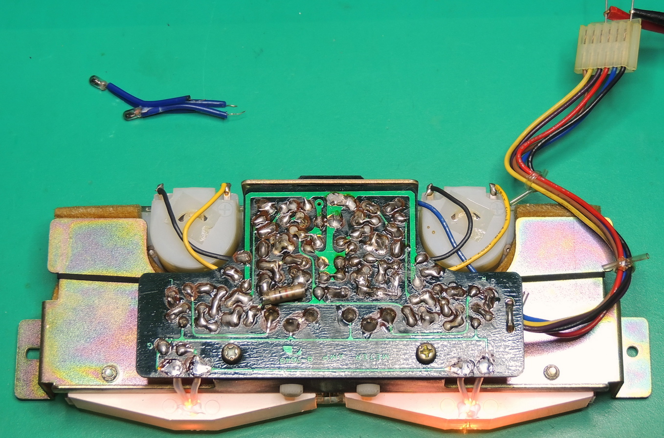
I also used a dab of white electronics grade silicone RTV where the lamps and heat shrink tubing enter the reflector housing to reduce any possible vibrations on the bulb.
Reassembly is basically the reverse procedure used for removal. Don’t forget to plug in the meter assembly connector, and also carefully guide the bezel into the faceplate as it may not exactly center up on it’s own.
Hi Barbouri, very nice project on a rare system! I m having trouble with my 610 and will need to go into it. Do you have any advice which parts to use as replacements? As it seems that the used parts are of special construction but have common values…
Best regards from Germany
Denis
Hi Denis,
I replaced all the electrolytic capacitors on the power supply board with 5000 hrs @ 105C or better rated Nichicon or Vishay units. In the other modules and boards I only replaced the electrolytic capacitors in the power filtering sections, and checked the capacitors in the audio path.
I did not find any out of tolerance electrolytic capacitors in the audio path on my unit. Cleaning the switches and potentiometers made the biggest improvement in sound quality.
Greg (Barbouri)