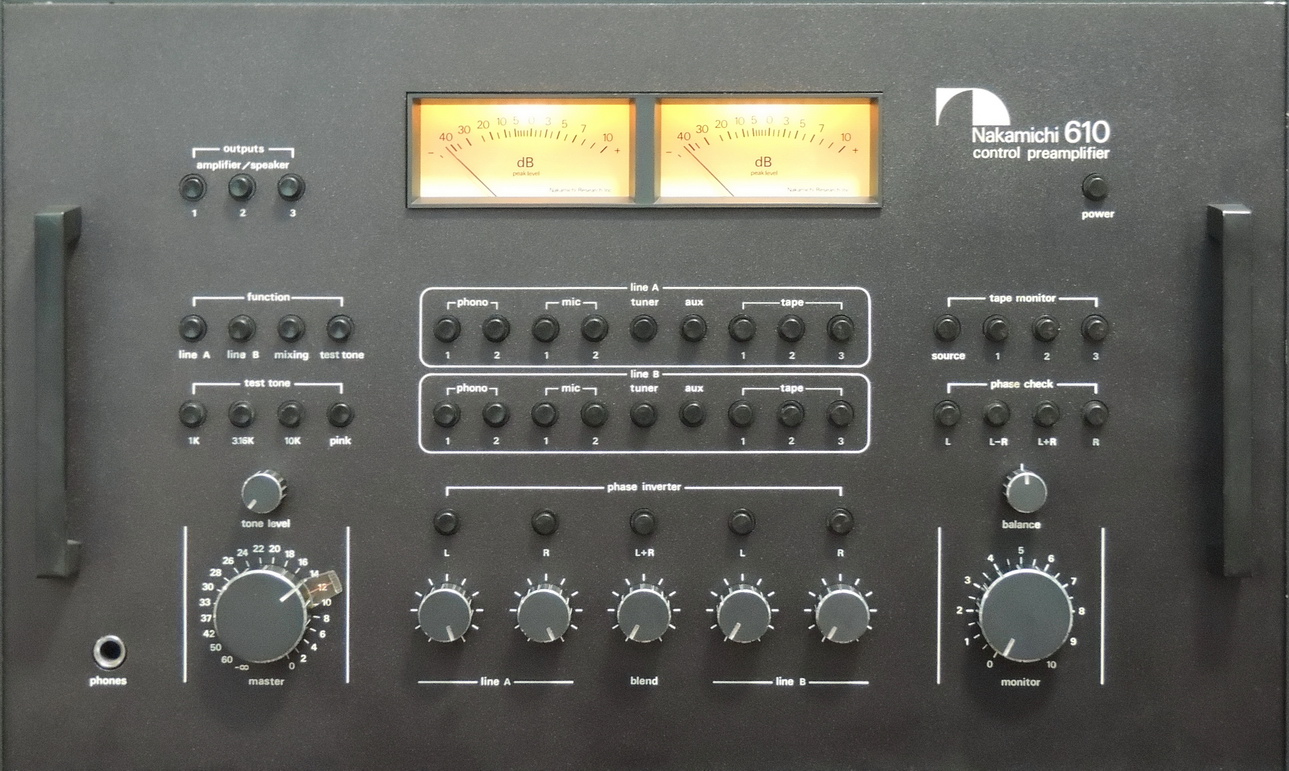
Nakamichi 610 Control Preamplifier Lamp Replacement

I did not take any pic­tures of the ini­tial refur­bish­ment of the Nakamichi 610 con­trol pre­am­pli­fi­er as it was main­ly clean­ing and capac­i­tor replace­ment. But as soon as I thought the work on all the com­po­nents of the System One rack had been com­plet­ed, one of the dB meter lamps failed in the 610 preamp.

Nakamichi 610 con­trol pre­am­pli­fi­er after restoration
Continue read­ing “Nakamichi 610 Control Preamplifier Lamp Replacement”

Milliohm Meter Version 1.5

Update to the Milliohm Meter Project

Updated V1.5 board assem­bly for the Milliohm Meter Project.
The Milliohm Meter board V1.41 is fea­tured in Scullcom’s Milliohm Meter Udpdate YouTube video.
I had already start­ed on the ver­sion 1.5 board update a week ear­li­er and was about to send the pro­to­type files out to OSH Park for man­u­fac­tur­ing, when I noticed a new Scullcom video thru my YouTube sub­scrip­tion notice. I was pleas­ant­ly sur­prised to see that it was an update to the orig­i­nal Milliohm Meter and it was fea­tur­ing the V1.41 board that I had designed. Louis had made some sim­i­lar updates to com­po­nents, so I quick­ly updat­ed the V1.5 board file to match before send­ing it off.

Continue read­ing “Milliohm Meter Version 1.5”

Milliohm Meter

MilliOhm Meter Display 0.025ohmThe Milliohm Meter Project

I built this mil­liohm meter sev­er­al months ago which is based on a project by Scullcom Hobby Electronics and pre­sent­ed on YouTube.

Louis at Scullcom Hobby Electronics has a new video updat­ing the mil­liohm meter, and fea­tures the board I pro­duced in this post.
NEW Link to updat­ed video on YouTube
NEW Version 1.5 board avail­able at OSH Park requires addi­tion­al 0.01 uF ceram­ic capac­i­tor, 2 pin head­er, and 250 mA PTC fuse.
NEW Updated project post with Milliohm Meter ver­sion 1.5 board.

It uses a 4 wire kelvin mea­sure­ment sys­tem that sup­plies a pre­cise 100 mA cur­rent to the device under test using one pair of leads, and then mea­sures the volt­age drop across the device under test using a sec­ond pair of leads.
As designed it can be used to mea­sure low resis­tances of under 2 ohms (Ω).   Some of the design changes I made to fit my needs were:

  • Change the num­ber of resis­tors need­ed in the cur­rent source circuit
  • Use high­er pre­ci­sion resis­tors with a low tem­per­a­ture coefficient
  • Add sep­a­ra­tion and shield­ing between input, out­put, and sup­ply circuits
  • Use low­er ESR and high­er val­ue capac­i­tors for the MAX680 pow­er supply
  • Add addi­tion­al decou­pling capac­i­tors on the INA106, and MAX680 IC’s
  • Change the volt­age reg­u­la­tor from a TO220 pack­age to a SOT-223 package

Continue read­ing “Milliohm Meter”