

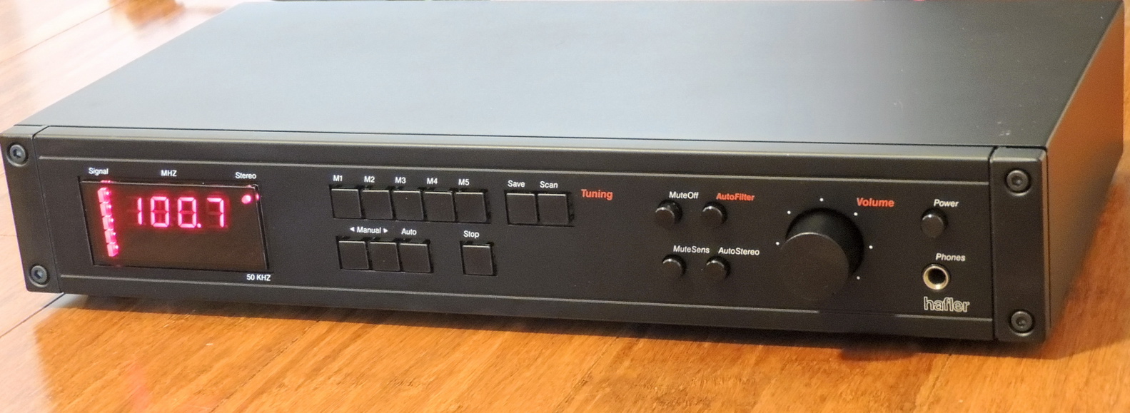
After repairing the Nakamichi 610 FM Tuner / Preamp back in late 2023, I have been on the lookout for a FM tuner for the workshop audio system. Since I already had the Hafler DH-110 Preamplifier, I set my sights on the DH-330 FM tuner which has the same styling as the 110 preamp.
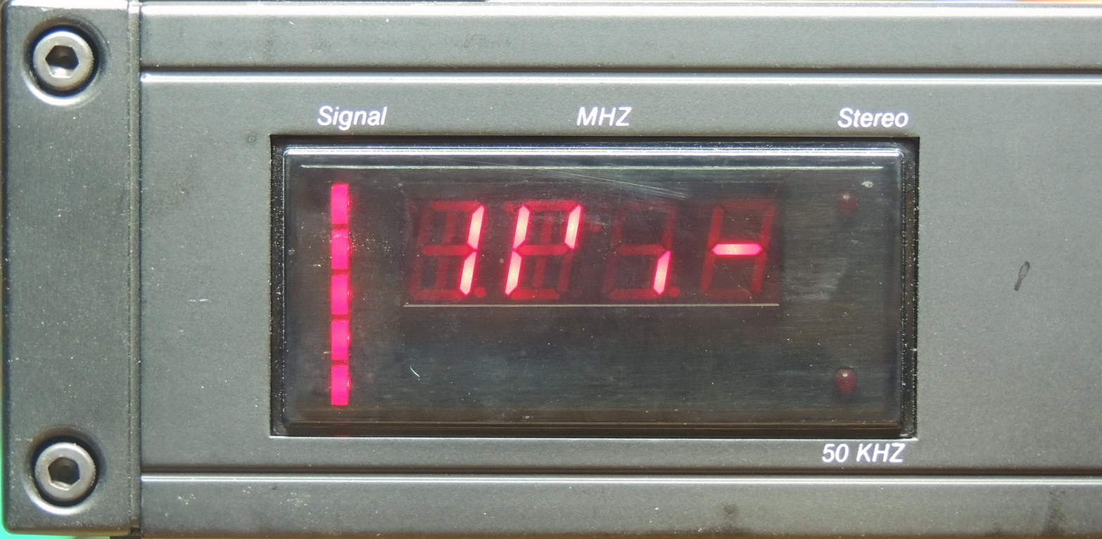
After looking for several years I finally came across an auction listing for a “DH330 Stereo FM-AM Tuner — Not Tested Parts Or Repair audio unit”. I was the high bidder at $36.00 with a reasonable shipping price. The unit looked to be in overall great cosmetic condition, but had around 50% of the frequency display segments not working. I also noticed from the auction pictures that the stereo indicator wasn’t lit up with a strong signal present. Even though the listing described this as an “FM-AM Tuner”, the DH-330 is a FM only tuner. Something easily overlooked by the seller as many of the component tuners of this era were AM-FM band devices.
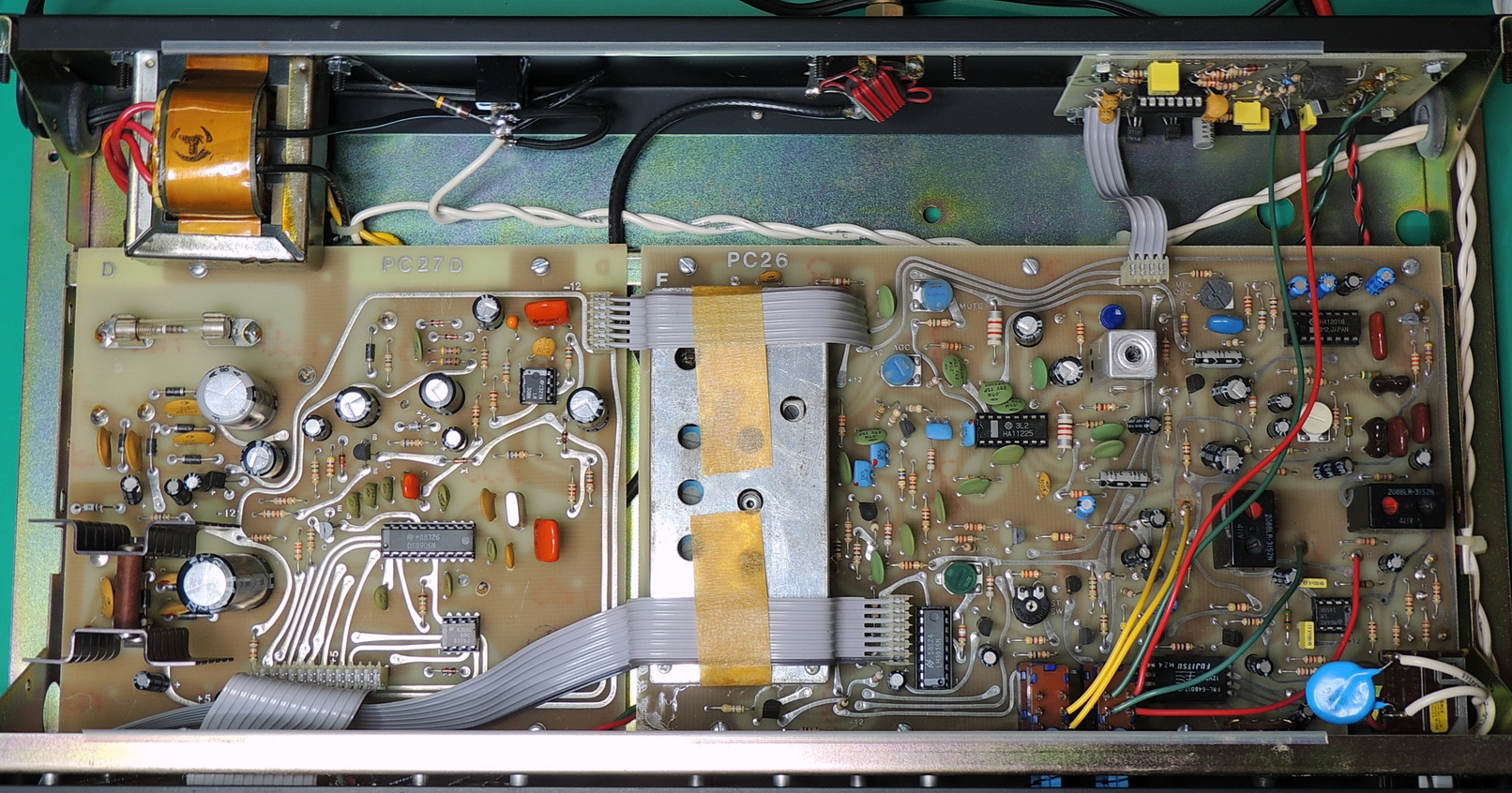
After receiving the unit I immediately opened it up to check for a proper fuse and gave it a though visual inspection especially looking for bulging or leaking capacitors. Looking at the date code on many of the IC’s this unit was built in 1985, making it over 40 years old.
The displays are a known issue on this model and based on how many of the segments were non-functional my guess is that this unit had seen many thousand hours of use.
The display is a NSM-4005A manufactured by National Semiconductor Optoelectronics division. The display is an integrated circuit board featuring a four digit red 0.5″ seven segment LED display with an onboard serial input display driver and a terminal area with pads and thru-holes.
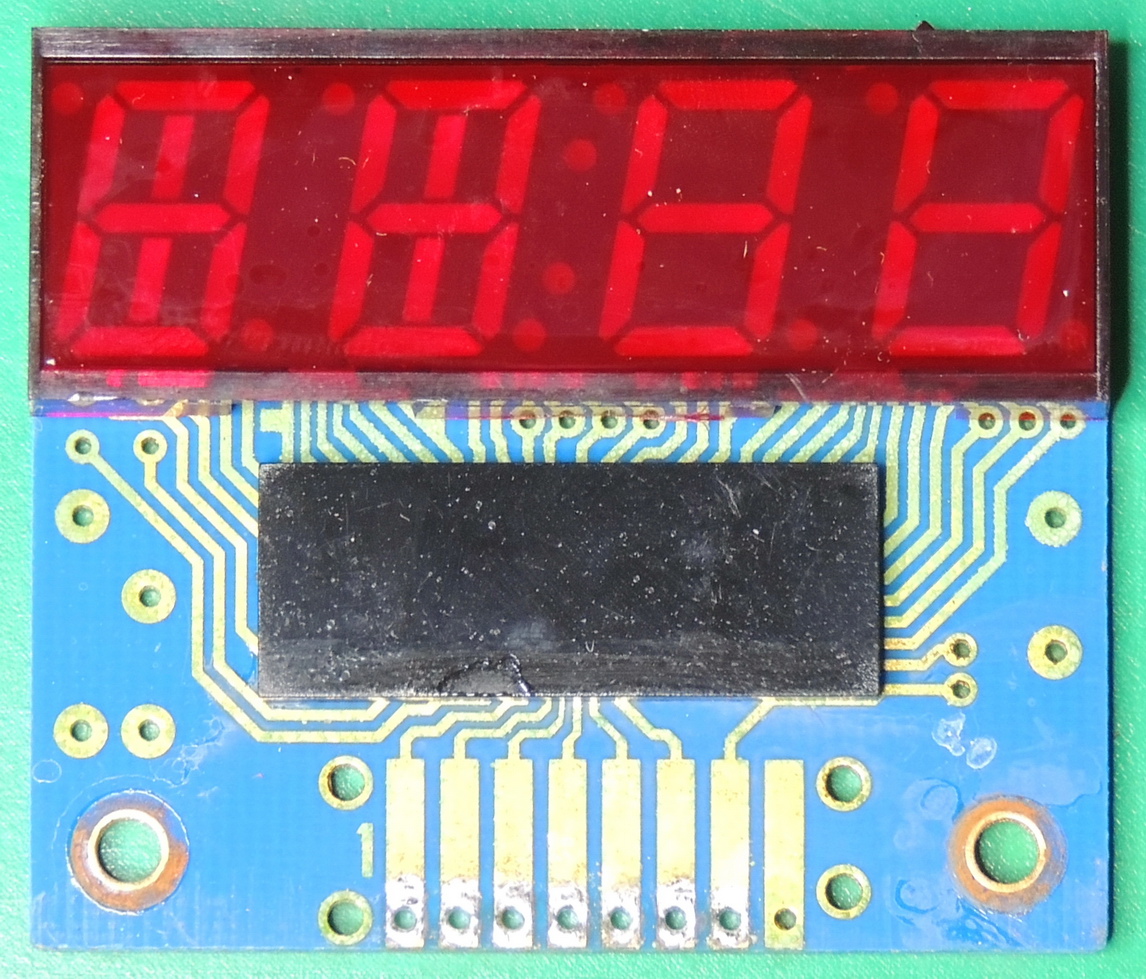
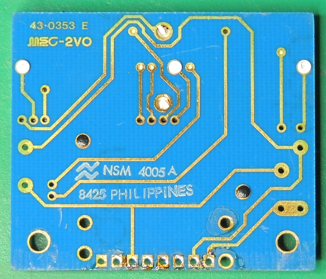
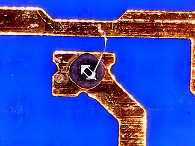
I did remove the red display filter and white light shield for the segments from the board to see if it might be possible to replace the individual segment LED’s. That would be a No, as the microscopic LED dies are bonded to the circuit traces along with microscopic wire from the dies to other circuit traces.
Unfortunately National Semiconductor quite suddenly quit production of optoelectronic products shortly after making this module.
I did consider trying to design and build a replacement module for a brief instant, but the time, money, and effort made me quickly place that idea on the back burner.
I was able to power up the unit an perform a quick functional check and it worked very well with the exception of the display and the stereo signal indicator. Based on that I decided it would be worthwhile to replace the 40+ year old electrolytic capacitors that had seen many hours if not years of on-time.
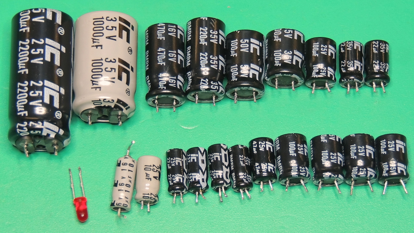
I ended up replacing 26 electrolytic capacitors, but stayed away from several capacitors in the RF sections of the board. Only power supply and audio path capacitors were replaced and the others were checked for capacity and ESR mostly in circuit.
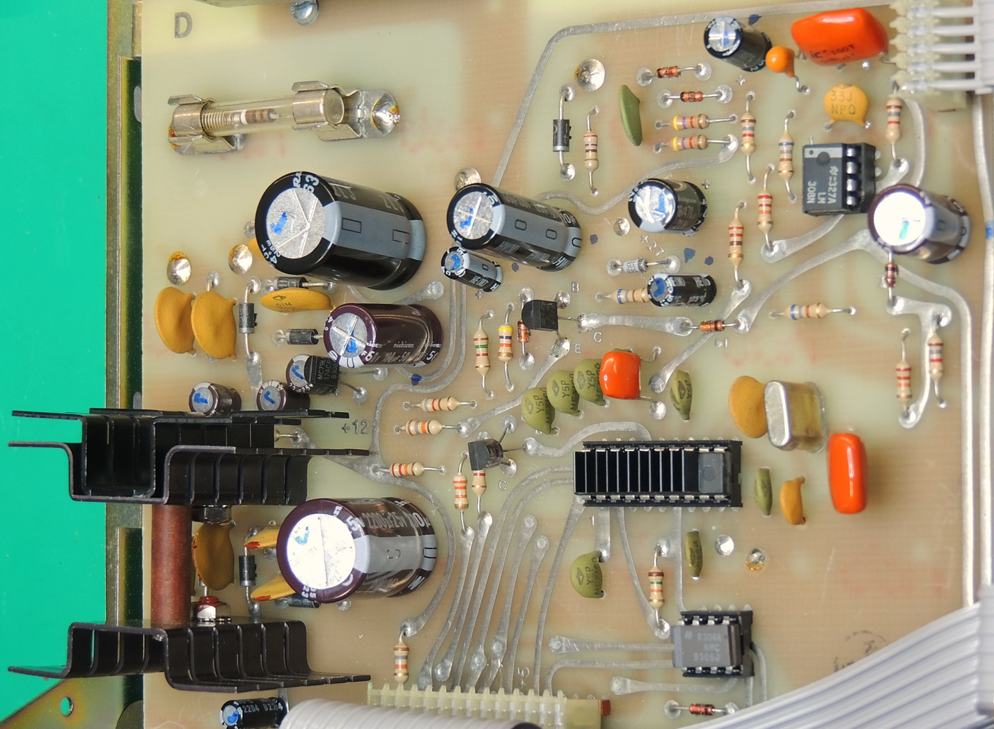
High quality low-ESR Nichicon capacitors were used on the power supply PC27D board, along with additional heatsink fins on IC101 LM317T the 12.2 volt regulator which operates fairly hot. I also added a heatsink to the 20 pin DIP IC104 DS8906N PLL Synthesizer IC which was also very warm / hot. All voltages were spot-on and AC ripple was virtually non-existent.
It was time now to figure out what was going on with the stereo indicator LED. I tested the LED out of circuit and it worked perfectly so was replaced. The stereo indicator is controlled by IC202 a HA12016 MPX Decoder IC pin 9 lamp driver.
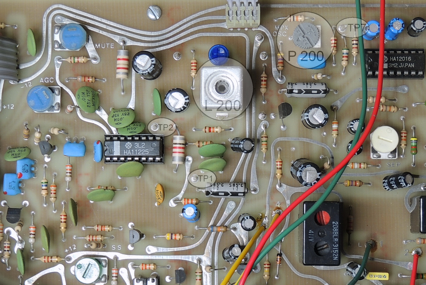
After a bit of research, I found an interesting thread over at audiokarma.org. I ended up marking the original location of P200 the PLL multiplex oscillator adjustment potentiometer. Then checking the solder connections which were good and then cleaning the potentiometer with DeoxIT D5 cleaner and then adjusting the pot back to it’s original location. The stereo indicator was now working properly.
Not leaving well enough alone I decided dive a bit deeper into the rabbit hole and researched the specification sheet for the HA12016 IC. There is a procedure there for properly adjusting the oscillator. It requires removing the inputs from pins 2 and 12 which required lifting one leg of C220 and R206 then shorted the antenna input.
A frequency counter was then attached to TP7 and P200 was adjusted for 76 kHz ± 50 Hz. The new potentiometer position was only around 3–4 degrees off of the original adjustment, but I felt better knowing a bit more about how the circuit operated.
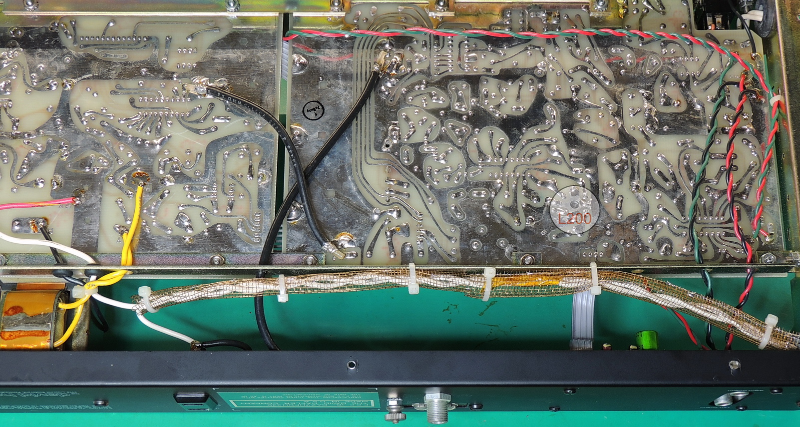
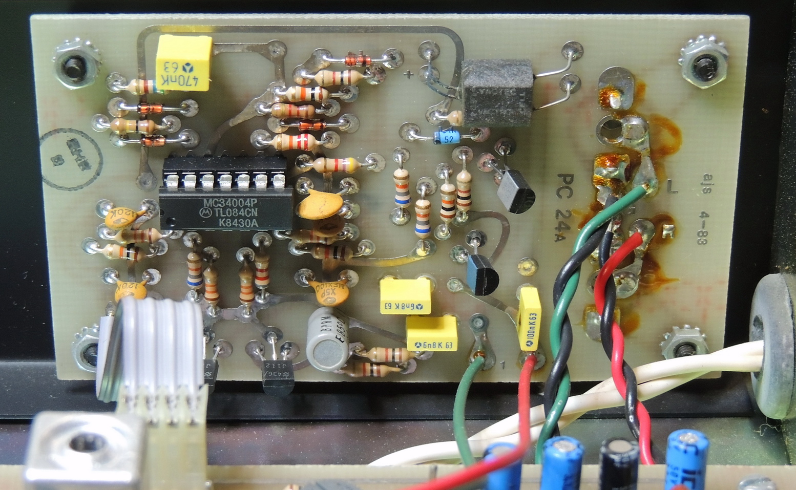
While I was at it I also adjusted the detector transformer designated L200. This is a dual tuning core transformer with an upper and lower physical adjustment. The easiest adjustment to get to is the upper core, but that controls audio distortion and generally should be left alone unless you have the proper equipment and expertise, which I do not have either of.
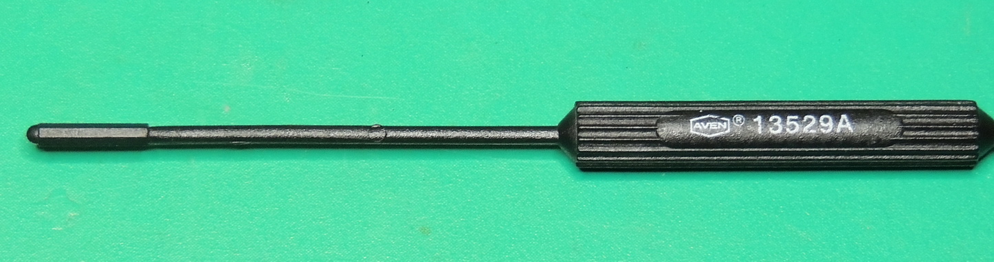
By connecting a multimeter measuring DC volts across TP1 and TP2 pictured above, and with the unit tuned on frequency to a strong station the lower core can be adjusted for close to a zero volt reading on the multimeter. Be sure only the bottom core is adjusted and use a proper non-metallic adjustment tool for this procedure. There is a small hole in the circuit board to allow access from the back side of the board if a multi-core adjustment tool isn’t available.
After searching many weeks for the obsolete display, I accidently came across an Ebay seller with some “Kalex Digital Clock Displays” with a part number matching my failing unit. I took a chance and placed an order, and now had to wait for it to arrive.
While waiting I did a lot of cleaning of residual flux from circuit boards and also cleaned all of the IC pins and sockets using DeoxIT D5 contact cleaner. The volume potentiometer and headphone jack were also cleaned. Interestingly the rear RCA line out jacks feed through contacts on the headphone jack when no plug is inserted and could be a source of noise if not cleaned.
The screws holding the power transformer to the back panel were a bit loose allowing it to sit at an odd angle which was corrected by gently twisting the transformer and tightening the screws snugly.
I do not know what to think about the 4.7 Megohm resistor tied to ground from one of the AC line terminals of the AUX AC power jack on the back panel. The power cord is non-polarized so this resistor has a 50/50 chance of being connected to line or neutral of the AC power cord. This is how it was originally designed according to the schematiics.
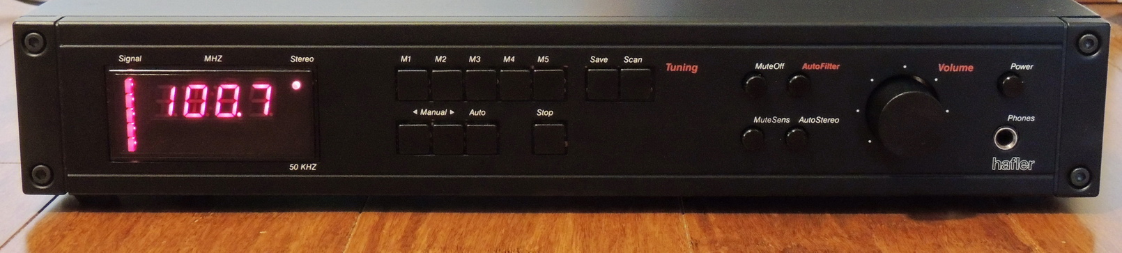
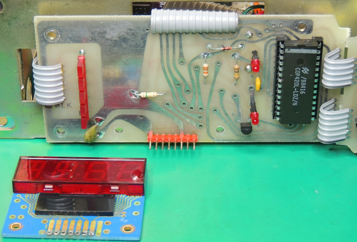
The display arrived and I replaced the original discrete wires with a pin header and then soldered the new display to the pin header. Upon power up the display worked properly just like a new unit.
I am very pleased with the new addition for the workshop audio system and it looks great paired with the DH-110 preamp.
Now I am on the search for a Hafler SE-150 CD player …