

My latest project is a prototype I2C RGB LCD display board with added EEPROM and some other extras.
I decided to do some more work on the Programmable Voltage Reference project, after a long run of test equipment cleanup and repairs.
A specific area of the project that I wanted to tackle was the automation of the calibration procedure, and the possibility of multiple calibration offsets at different temperatures. Another current limitation of the PVR is that it can only directly display the voltage set point.
It would be fairly easy to cycle thru the Set point, Output voltage, Voltage difference, and Mode by just using the existing display and update the display once a second with the next value. Or even dedicating another push-button switch to cycle thru the displays.
The characters on the RGB-LCD display are significantly smaller and will be harder to read from a distance, but can display much more information all at once. Another advantage is using the RGB color back-lighting as a status indicator instead of the rotary encoders RGB led.

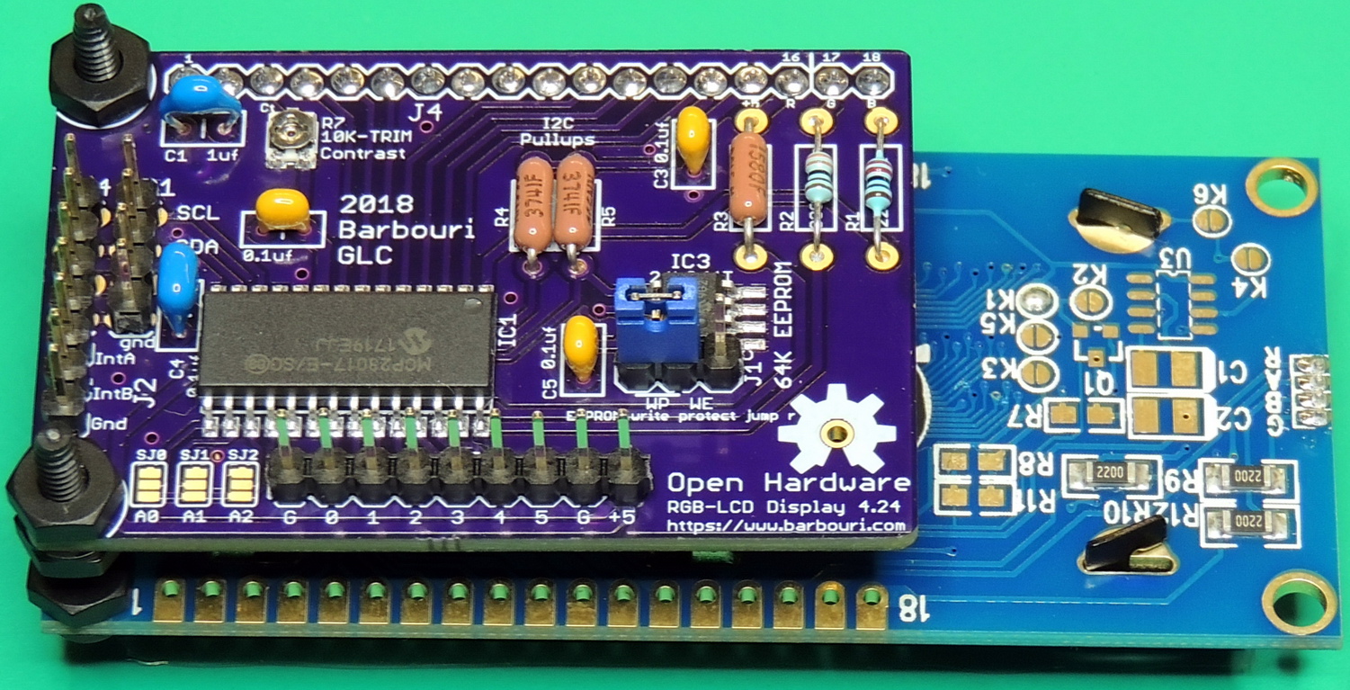
I changed around my existing V4.23 RGB-LCD display board by removing the DS3231 RTC (Real Time Clock) IC and added a Microchip Technology 24LC64T‑I/SN 64K EEPROM chip. I also made some other changes to the board such as adding an extra I/O pin and +5 to the JP3 header. The EEPROM footprint is the same as the larger 128K EEPROM 24LC128‑I/SN I.C. which would make it easy to upgrade to a larger EEPROM in the future.

So far the board is working as expected, along with the Write Protect jumper. I am using the Arduino External EEPROM Library by JChristensen, along with the MCP23017 libraries from Adafruit.
I have also recently designed an inline EEPROM board for my existing PVR units with the 4 digit 7 segment displays.
Boards have arrived from OSH Park.

The next part of the project is to work on changing the code to use the external EEPROM, instead of the run-length encoded data stored on the internal Teensy 3.2 EEPROM.
After finishing the Teensy code the next task is to automate the calibration offset measurements and storing the data into the external EEPROM. My current plan is to use Excel to set the PVR output voltage using serial comm’s and reading the voltage with my Keithley 2015 and the internal Teensy ADC. Then calculate the difference from the set-point and write the offset values for the output DAC and the Teensy internal ADC using the comm port.
After calibration is completed for all 4,095 settings, the system will verify the output with offsets applied.
OSH Park shared I2C RGB LCD Display 4.24 W/eeprom project
EagleCAD Schematic and board files ZIP for Display V4.24 EEPROM
Hi,
This board is for RGB backlight negative LCDs?
Which one did you use — Adafruit 399?
Thanks
Alex
The I2C Display board should work with any HD44780 based text display.
I used the #399 RGB backlight negative LCD 16x2 display, but the board will work with monochrome displays and 20x4 RGB displays such as the #498.
Greg (Barbouri)
Thanks Greg.
I have assembled two of these, but I cannot make them work with any screen. These are detected:
I2C scanner. Scanning …
Found address: 39 (0x27)
Found address: 80 (0x50)
Done.
Found 2 device(s).
but the screen 16x2 is not coming up.
Assembly is very simple so I feel I am missing something?
Thanks
Alex
OK, it seems like I have a faulty Sparkfun Arduino Pro Mini 5V. It does not work with this LCD Board, but Arduino Nano works just fine.
Hi Alex,
The first thing to check is that there is only one pair of I2C pullup resistors in the circuit. I usually use 10K ohms.
I have also found that some displays need a long time to start up, and by pressing the onboard reset on the Pro Mini it will communicate.
Greg (Barbouri)
Hi Greg,
You are absolutely correct — this is not Pro mini. Pressing RST button helps, but sometimes I have to press it many times without any luck. I can see that in Millivolt Meter project you soldered a cap between RST and GND? 0.1 uF? Does it help? Maybe there has to be a delay () in void setup () before LCD init?
Alex
Alex,
I used a 2.2 uF capacitor from RST to GND on the MV Meter project display to keep the micro from starting before the display.
For the cap I attached it using some IC socket jacks, so I could unplug it easily from the pins on the micro for transferring programs.
I have had some displays startup with no problems, and others that require the capacitor or reset button every time.
Greg (Barbouri)