

Building a 4–20mA current transmitter and receiver for some upcoming automation projects.
After a bit of online searching for a precision 4–20 mA circuit tester, I decided to build my own version.
I based my transmitter off of an YouTube video by youtuuba. It was a long but very detailed video on how he built a simple 4–20 mA transmitter. The design is based on the Burr-Brown (Texas Instruments) XTR105 monolithic 4–20mA, 2‑wire current transmitter IC.
The circuit in the video was a very basic design with an emphasis on the smallest footprint possible.
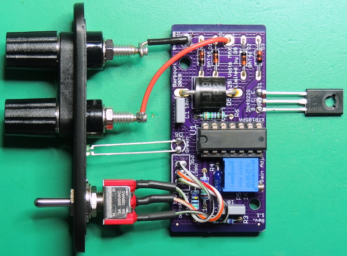
I was not constrained by size and decided to add reverse voltage operation and over-voltage surge protection, along with an external transistor to improve accuracy. I also used precision 250 Ω 0.1% ±25ppm/°C resistors for the setpoint resistors R1 and R2.
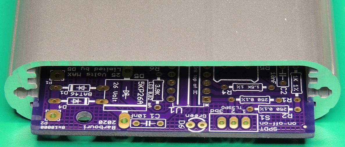
After the first prototype board was completed and tested, I decided to slot mount the PCB in a Hammond 1455B802 aluminum enclosure. The revision 1.2 board size was changed with only minor adjustments to some traces to fit the case.
With the reverse voltage protection diode bridge, it doesn’t matter which terminal is connected to the + or — loop connections.
The transmitter is loop powered, and requires an external 12 to 25 volts DC supply for power.
I used some BAT46 Schottky 150mA diodes for the bridge circuit with a forward voltage of around 520 mV @ 20 mA of forward current. Total loop voltage drop thru the bridge at 20 mA is only around 1.04 volts.
After the diode bridge circuit is a Vishay 5KP26A-E3/54 uni-directional 26 volt transient voltage suppressor (TVS) diode. I ended up using a 5,000 watt TVS diode in a P600 package, because that was the only thing in stock. A 500 watt TVS diode would be more than adequate for this circuit. I also picked a Reverse Standoff voltage of 26 volts, as I only planned on using a loop voltage of 24 volts. The XTR105 is rated for loop voltages of up to 36 volts which can be accommodated by increasing the Reverse Standoff voltage of the TVS diode to the next value over the required max circuit voltage.
I used an external 2N4922G Bipolar NPN transistor to isolate the majority of the power dissipation from the precision input and reference circuitry of the XTR105 IC. This is recommended in the data sheet for improved accuracy and extended temperature range.
The transistor is mounted to the aluminum case with a nylon 4–40 screw and nut with a thermal pad providing electrical isolation between the two. I also used a 1/8″ thermal GAP pad between the XTR105 IC and the top of the case to provide additional thermal stability.
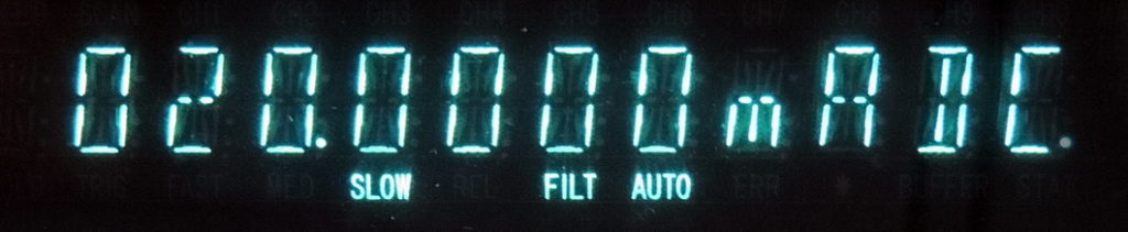

The gain adjustment potentiometer is adjusted for a loop current of 20.000 mA with the switch set to 20 and a loop voltage of 24 volts. I use a 250 ohm resistor in series with the loop while adjusting the gain.
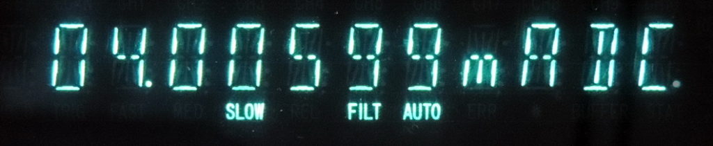
Once the 20 mA setting is calibrated, check the 12 and 4 mA switch settings to verify that the readings are within 10 µA of the setting. When connected to an operational loop the front LED will illuminate indicating the circuit is operational.
The front panel switch is a C&K 7103SYZQE single pole double throw switch with three positions (On-Off-On). Front panel connections are Pomona double binding posts that will accept either standard banana plugs or wire connections. Both posts are black in color as the diode bridge circuit will allow any polarity connection.
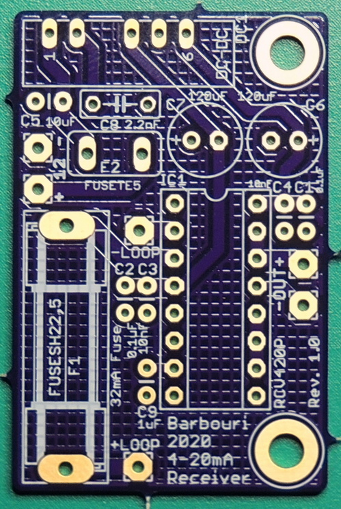
The next project in progress is a 4–20 mA receiver with 0 to 5 volt output, based on the Burr-Brown (Texas Instruments) RCV420 current-loop receiver IC.
Component information is embedded in the EagleCAD board file component attribute setting.
EagleCAD V7.7 board & schematic ZIP file for 4–20mATransmitter
OSH Park printed circuit boards for the 4–20mA Current Transmitter