Restoring a Power Designs Inc. 6010D power supply
I usually keep an eye out for for Power Designs Inc. power supplies that are in need of some repair and some TLC, and I happened across a PD 6010D unit up for auction. Luckily I was the only bidder and purchased it for slightly more than the shipping cost.
It was a fairly sad looking unit with a lot of orange/brown tinted grime everywhere, along with some spider webs, stickers, and sticker residue everywhere. The supply was advertised as ” Unit does need several minutes to arm up but appears to be functioning”.

After receiving the power supply, I checked it for shipping damage. Surprisingly it was intact, even thou it only had a few layers of loose bubble wrap, and a few pieces of air filled plastic pouches in the box. The auction photos didn’t do justice to how incredibly grime coated it actually was.
I was somewhat tempted to try and power up the supply, but after the rough shipping common sense prevailed and I did a proper inspection first.
First checks were the power cord and fuse. I then checked the transformers primary winding thru the power cord, and it’s isolation from ground. The transformer’s primary winding resistance was 6.1 Ohms and greater than 1 GOhm resistance to ground, so far so good. I then took the cover off to check inside the unit.
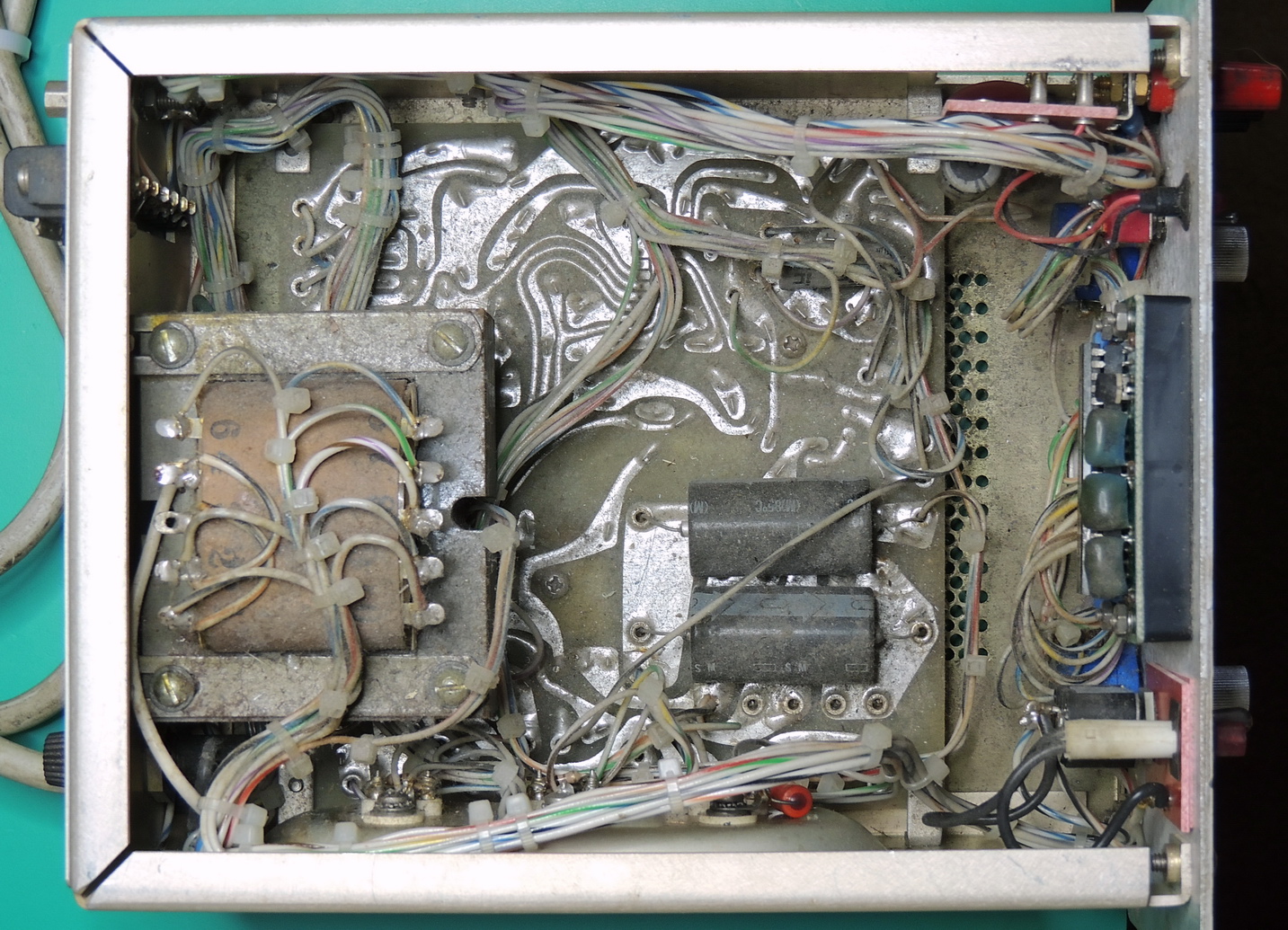
The good news is that I didn’t find anything loose or damaged inside the case. Not really any bad news as I somewhat expected to find some dust and grime inside the case, just a bit more than I thought with some trails of gunk where liquid had dripped or splattered inside.
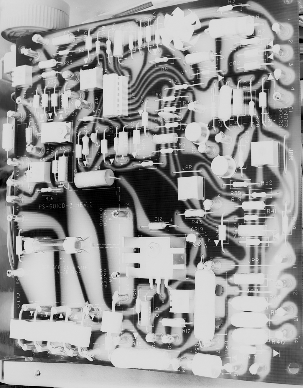
The areas where splatter and drips were bridging across traces may have something to do with the “slow warm up” auction description. Time to start cleaning.

After checking the main board capacitors with my PEAK atlas ESR+ capacitor tester, and finding that the existing capacitors were at the lower end of their tolerance rating I decided to replace them. I went with Vishay long-life series capacitors rated for 10000 Hrs @ 105°C. I also added a small square of some 20 mil thick FR4 sheet under the 2,200 uF capacitors for some extra isolation.
I disassembled the front meter, and removed the red bezel which was sitting at an odd angle in the cutout. The odd bezel angle was due to how the bezel was not originally machined at the proper angle. After removing most of the scratches on the bezel with Novus plastic polish, I was able to reassemble the display and bezel with some plastic shims to even it out.

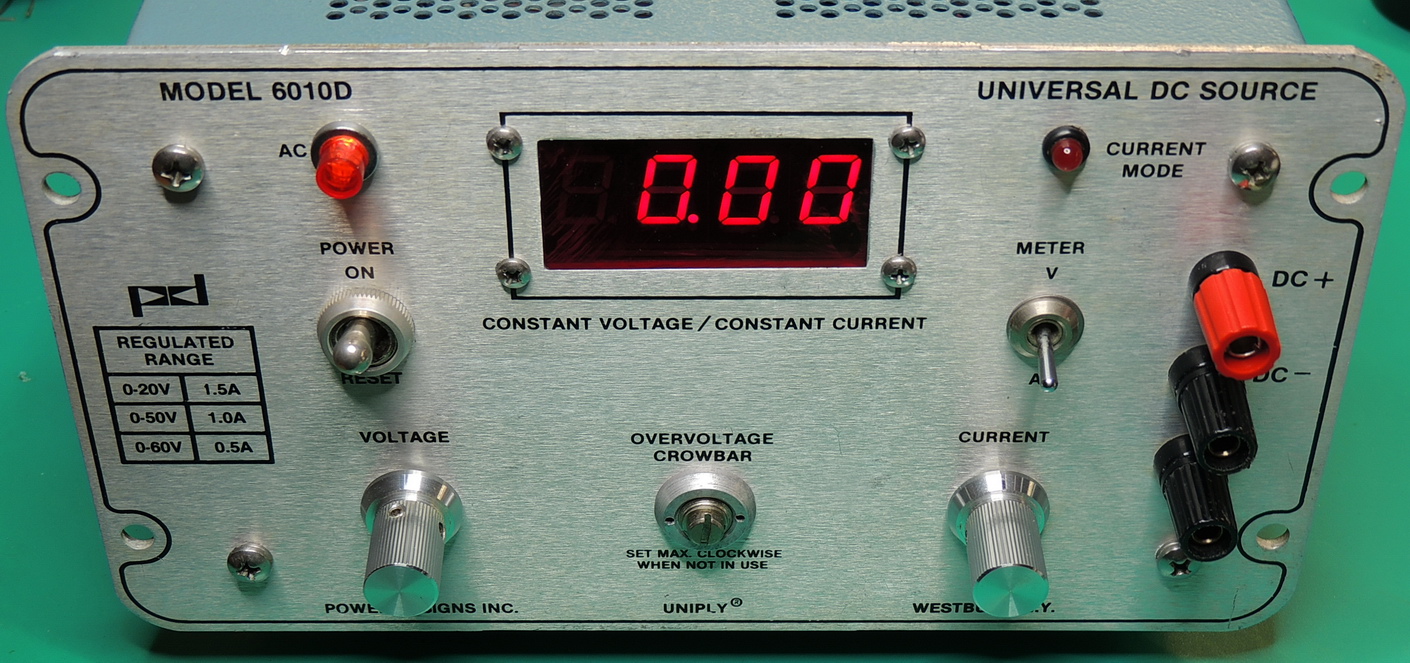
So far I haven’t been able to find any documentation on the PD 6010 series of power supplies. The PD 6010D has a nearly identical front panel compared to the PD 6050D with the exception of the printed “Regulated Range” values and model number. The back panels are also similar with some differences in labeling. The case length of the PD 6050D is 12″ (305mm), and the PD 6010D length is 9.2″ (234mm). Externally those are the only obvious differences between the two models.
The 6050D internal layout is quite a bit different, with many components mounted off of the main board.
I was able to find out which trim potentiometers were used for the front panel meter calibration by tracing their connections and comparing it to the 6050D schematic.
R53 is the meter current calibration which is adjusted at full output current (1.5 Amps). And R54 is for calibrating the full scale meter voltage which is 60 volts on the 6010D.

I have a future meter replacement project in the works for both the 6010D and 6050D supplies so knowing location of the calibration pots will be important for that project.
After reassembling the unit and completing some performance testing, I started on cleaning the outside case and front panel. The stickers and adhesive residue came off fairly easy, and left rectangular areas of clean anodized aluminum and paint. I do not know what this unit was coated with, possibly some type of lacquer or resin, but It took me around 6 hours to finally get it clean enough to meet my standards. The good news is that whatever type of grime that was on it did an excellent job of protecting the surface underneath it.

After calibrating the front meter and performance testing all three of the output ranges, I was very impressed with this lower wattage version of the 6050D. As usual the ripple voltage on all three ranges at full current was almost non-existent, and set output voltages were extremely stable over varying load conditions.

I am still wondering why this model wasn’t branded with a 6015D model number since it’s maximum output is 60 Volts at 1.5 Amps. That would have matched the ongoing model number structure.
I have also been curious if the PD 5015D power supply’s internal board and schematics are a close match with the 6010D’s?

Parts are on order for the upcoming meter upgrade, so I will be revisiting this unit hopefully in the near future.