

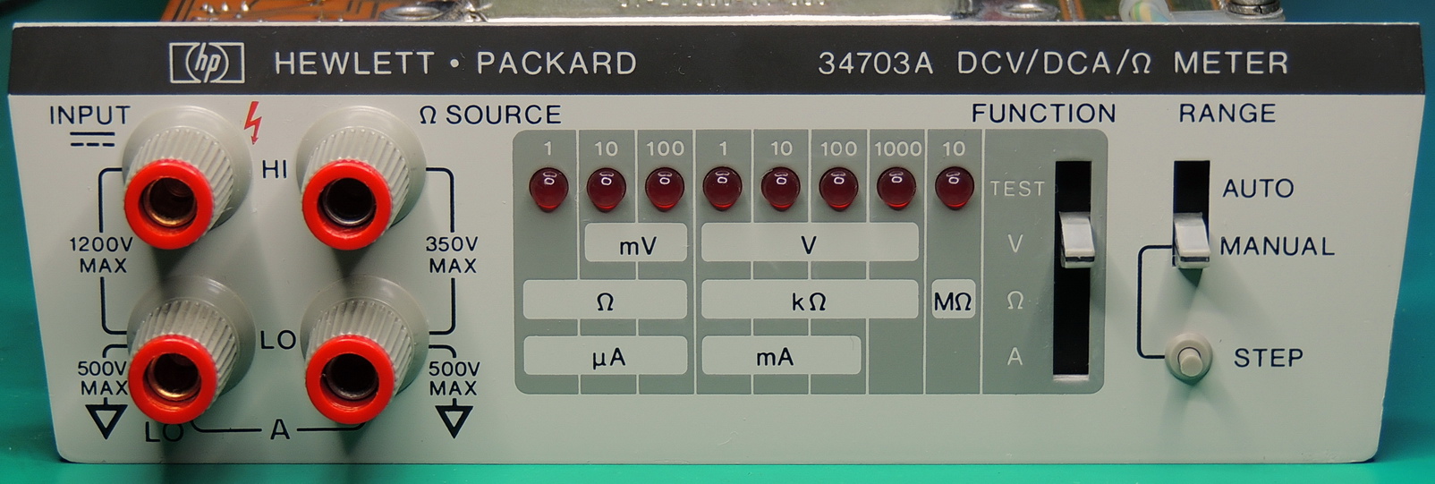
Cleaning up and photographing a Hewlett Packard 34703A DCV/DCA/Ω Meter plugin section of a 3470 measurement system.
I recently came across this HP 34703A module at an exceptionally reasonable price. The last time I worked with this measurement system was 42 years ago, so I wanted to document it and see what was inside, and how it worked.
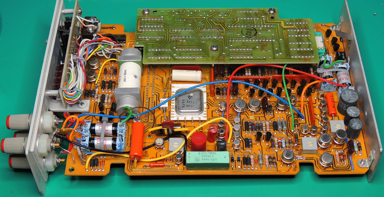
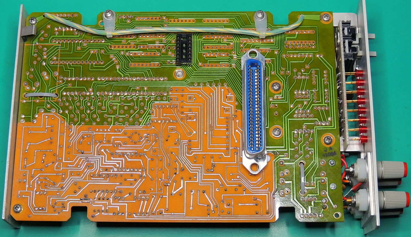
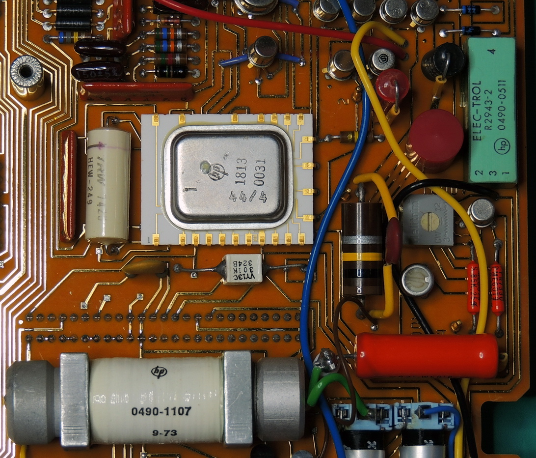
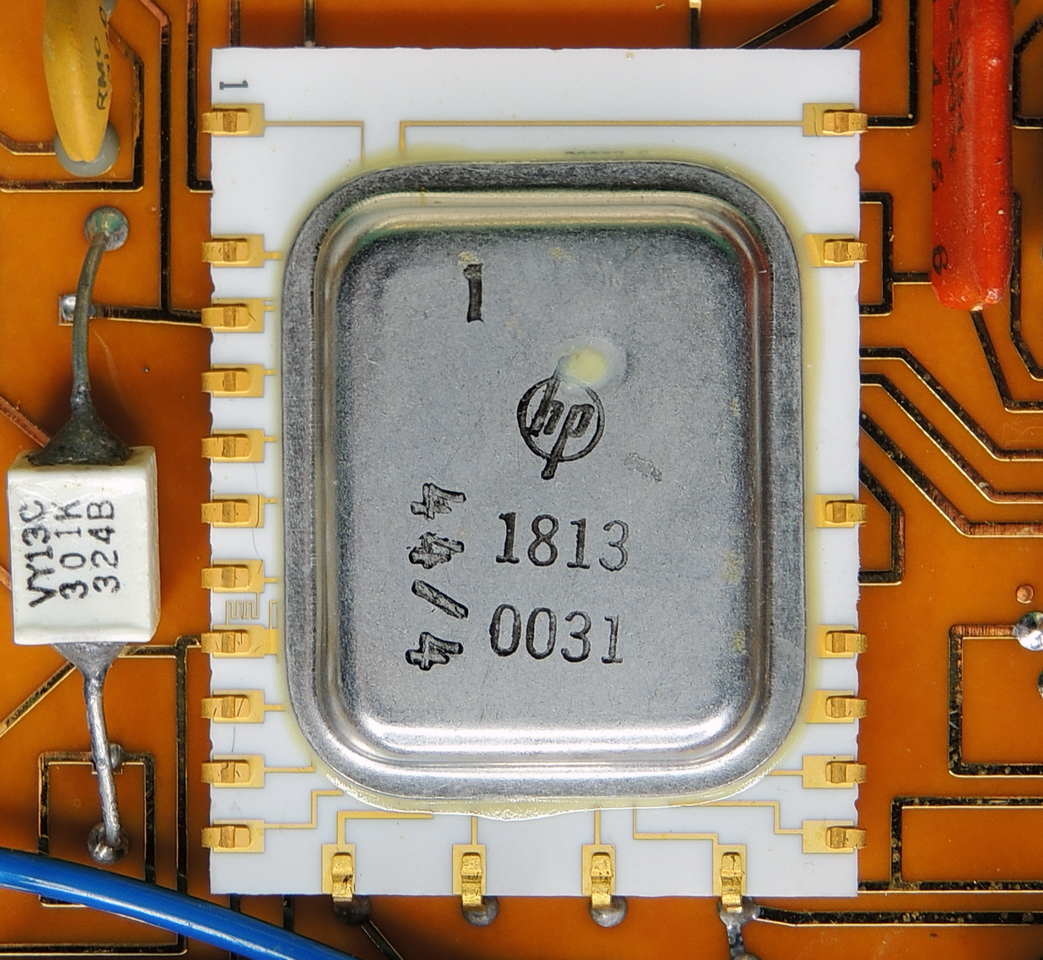
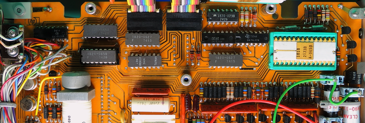
It is filled with plenty of HP goodness. Six relay modules for automatic range switching and auto-zero, laser trimmed resistors, precision discrete components, and a hybrid integrated circuit amplifier with a switched feedback network for establishing gain.
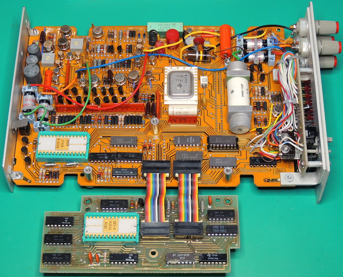
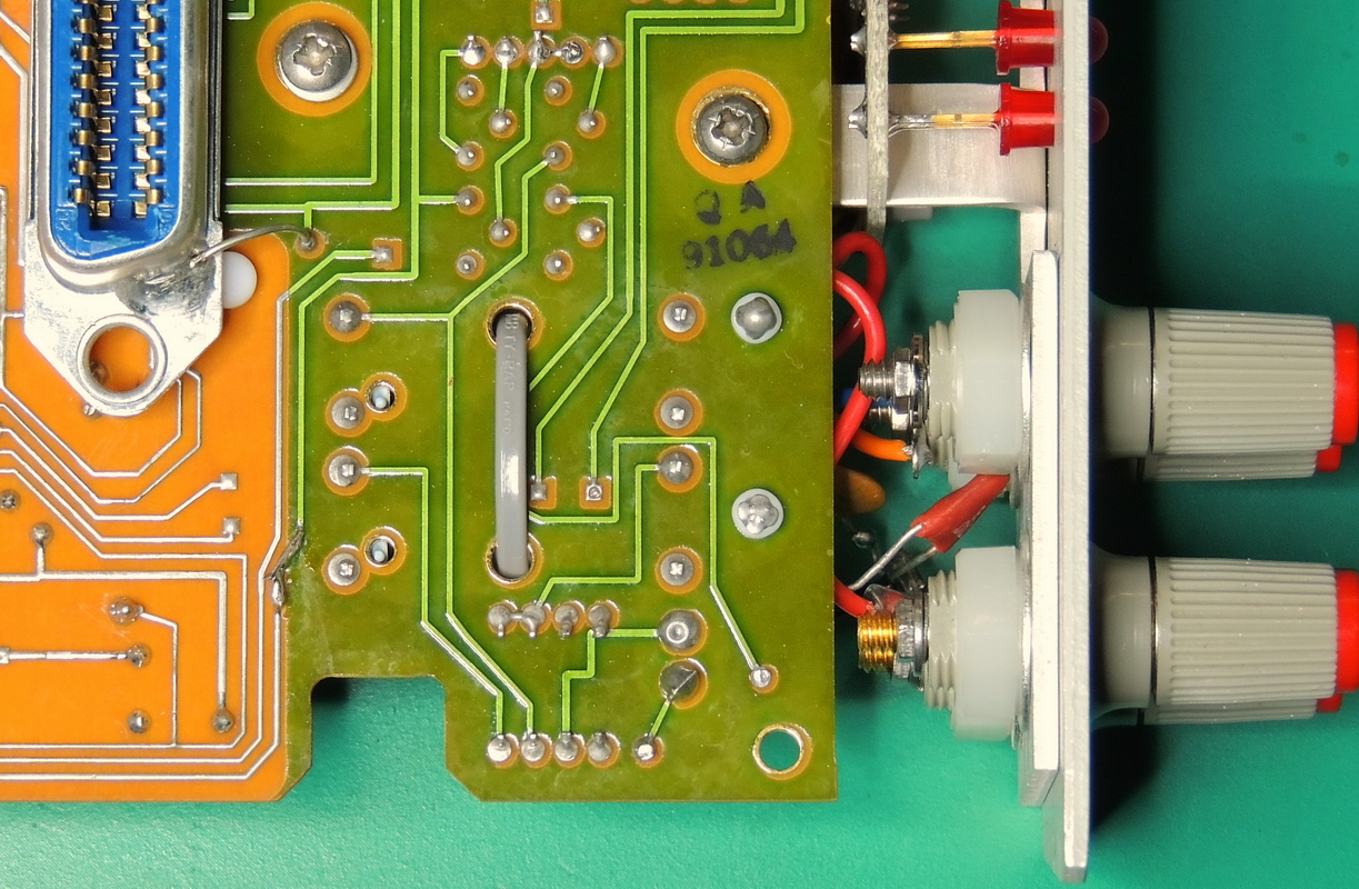
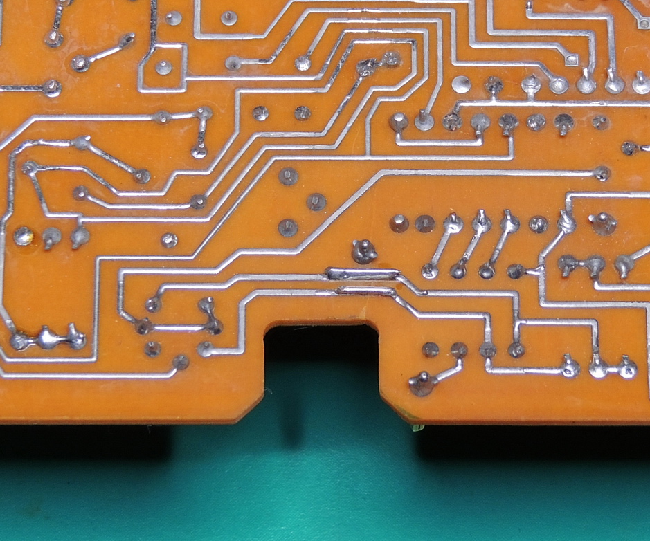
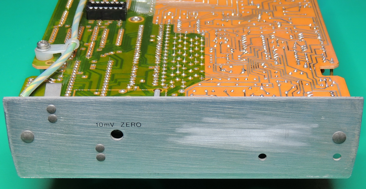
Traces on the top side of the board are gold plated for corrosion resistance, and the solder mask is removed from bottom side areas, along with PTFE insulators to reduce leakage currents in high impedance areas. It is a wonderful piece of engineering.
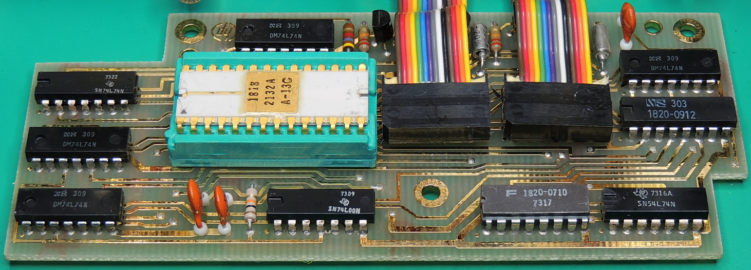
The 34703A has some impressive specifications for it’s price point and the time it was designed and produced. From the date codes on the IC’s it seems that this unit was built in late 1974.
Some of it’s capabilities include, 10-mV and 1‑ohm full-scale ranges, and also self test, autoranging, and current measurements to as low as 1 µA full scale. This is a plug-on module and is part of the 3470 measurement system. When used with the HP 34750A display section it can display 5 ½ digits on the LED readout.
I did notice several similar components that are also used in the HP 3456A Digital Voltmeter , such as the large reed relay with metal mounts. The part numbers are slightly different, but that may be due to something such as a different coil voltage.
Unfortunately, I haven’t been able to find a free downloadable version of the user/service manual for this module. If I can find a reasonably priced 34750A display module, I might purchase one of the manuals on CD for this unit.
There are several different revisions of the display and Option H02 A3 logic boards installed in these units. This unit has a Rev E main board, a Rev B H02 A3 board, and a Rev C display board. There are several Service Notes available for this module with minor upgrades to improve reliability, such as adding a bypass capacitor, or changing a resistor value on some of the earlier boards. One item that seems to be common and is evident on my main board is small hairline cracks traveling from where the mounting brackets attach the board to the case. Mine seems to have been patched with small wires soldered across the traces in the affected areas.

I have done some limited testing on this unit, such as applying 5 volts to the 5 VDC buss with a reasonable current draw for the IC’s on board, and a LED lit up on the front panel. I also tested most of the capacitors in-place on the board with no issues. So all looks well so far
Hopefully I will have an update at some future date, if I can get this paired up with a working display.