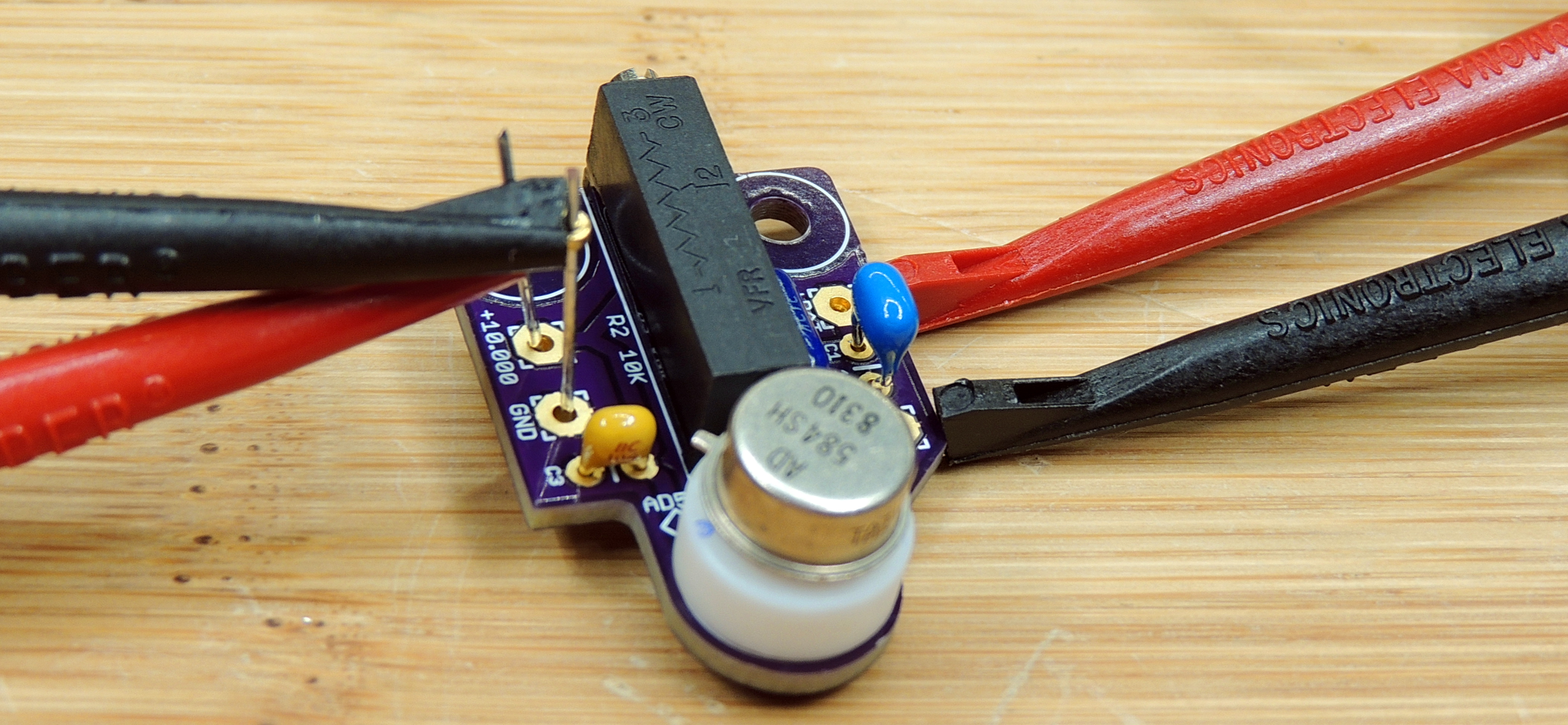
Building a 10 volt reference using some vintage AD584 IC’s from 1983.


Restoring vintage electronics along with designing and building new circuits. One eye looking into the past, the other looking into the future.
Building a 10 volt reference using some vintage AD584 IC’s from 1983.
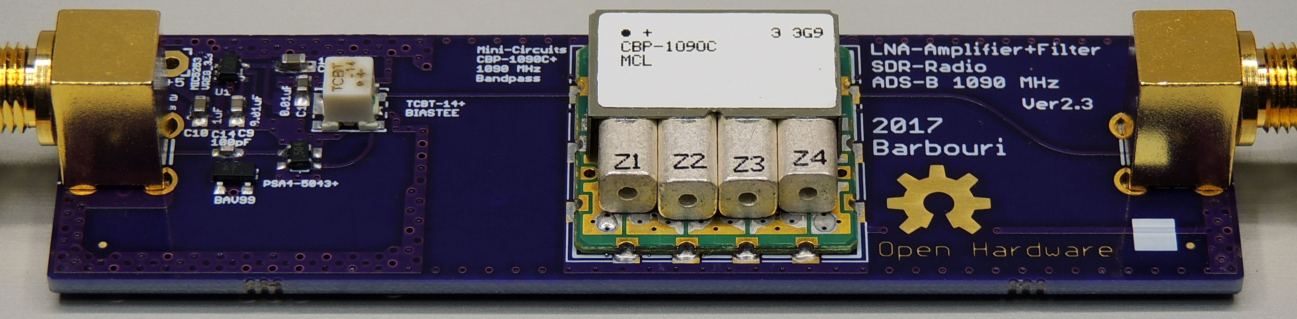
A project to design and build a Low Noise Amplifier (LNA) and 1,090 MHz bandpass filter for receiving ADS‑B transmissions on a Software Defined Radio (SDR).
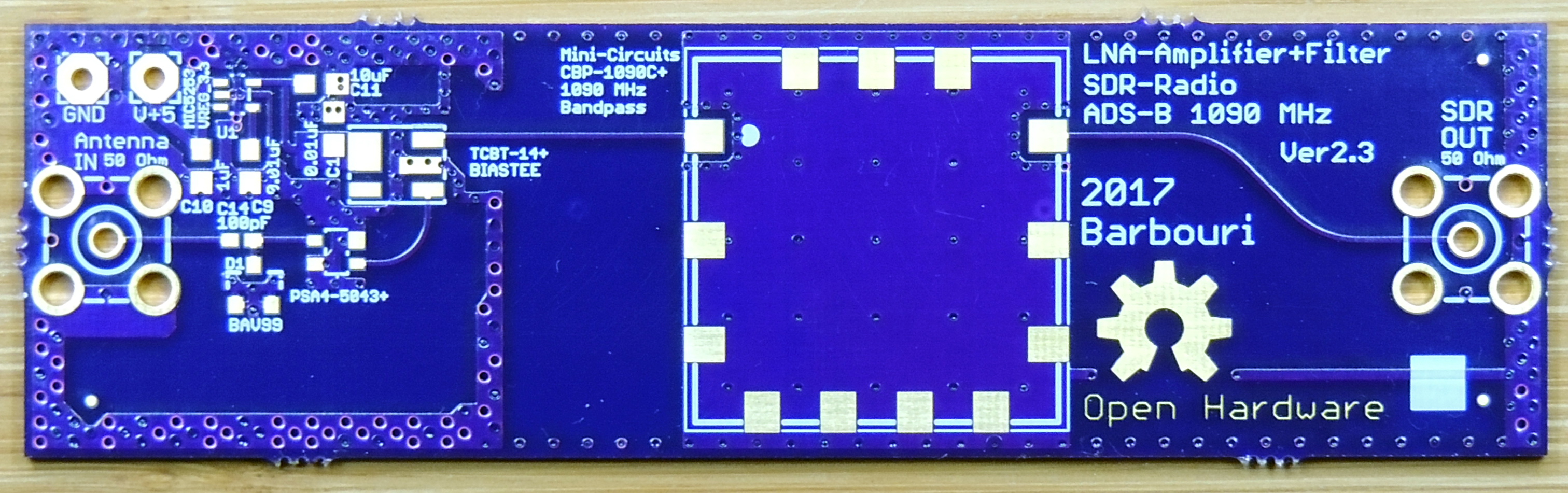
Continue reading “Low Noise Amplifier for SDR Radio ADS‑B Ver. 2.3 with 1090MHz ceramic filter”
Construction and circuit information for the DIY Open EVSE V4.23 electric vehicle charging system.

The DIY Open EVSE circuit board Version 4.23 is used for electric vehicle charging using the J1772 standard. It is an Open-source hardware project which uses the GNU General Public License and is based on the original designs by Chris Howell and Lincomatic.
Continue reading “DIY Open EVSE V4.23″